Vehicle control system

a technology of vehicle control and control system, applied in the direction of electric control, gearing, machines/engines, etc., can solve the problems of increasing the size of the planetary gear train, increasing the amount of energy that passes through the mechanical unit, and poor efficiency, so as to reduce the engine output

Inactive Publication Date: 2007-03-27
KOMATSU LTD
View PDF14 Cites 24 Cited by
  • Summary
  • Abstract
  • Description
  • Claims
  • Application Information

AI Technical Summary

Benefits of technology

[0029]The invention is provided with engine controlling means for controlling the engine and decelerating means for outputting a deceleration command according to its operating amount. In response to a deceleration command from the decelerating means, the engine controlling means reduces engine output torque which corresponds to an engine speed region including the engine speed NQ in the lower speed region and the engine speed NH in the higher speed region (see the engine output torque line indicated by broken line in FIG. 9). Accordingly, the tractive force-vehicle speed characteristic line WLQ in the lower speed region, the tractive force-vehicle speed characteristic line WLG corresponding to the direct region, and the tractive force-vehicle speed characteristic line WLH in the higher speed region are respectively shifted to a lower tractive force region in the tractive force-vehicle speed characteristic graph of FIG. 9 [(WLQ; WLG; WLH)→(WLQ′; WLG′; WLH′)], and vehicle speed determined through determination of a tractive force (FQ; FG; FH) required by a load is rapidly reduced in all vehicle speed regions [(VQ→VQ′); (VG→VG′); (VH→VH′)]. According to the invention, deceleration can be quickly done in all vehicle speed regions and a direct region can be set where power from the engine is transmitted through the mechanical transmission unit alone in the hydro-mechanical transmission.

Problems solved by technology

As just described, when hydraulic power flows in the reverse direction, a large flow of energy occurs in each element, resulting in poor efficiency.
As seen from FIGS. 14(a) and 14(b), if part of energy flows in the reverse direction, the amount of energy that passes through the mechanical unit will increase, and therefore, there arises a need to increase the size of the planetary gear train, which leads to a disadvantage in economical efficiency.
The vehicle control system having the output-split / input-split switching type HMT, however, suffers from the following problem, owing to the facts that the matching point MQ in the lower speed region and the matching point MH in the higher speed region need to be spaced at a certain distance in order to effectively form the direct region and that the all-speed control is employed for engine control.
Therefore, the output speed of the output-split / input-split switching type HMT cannot be changed by the shifting of the regulation line.
In short, this vehicle control system has the problem that there exists a vehicle speed region where vehicle speed cannot rapidly decrease even when the opening of the engine throttle is reduced in conjunction with deceleration.

Method used


Image

  • Vehicle control system
  • Vehicle control system
  • Vehicle control system

Examples


Embodiment Construction

[0045]Referring now to the accompanying drawings, a vehicle control system will be concretely described according to a preferred embodiment of the invention.

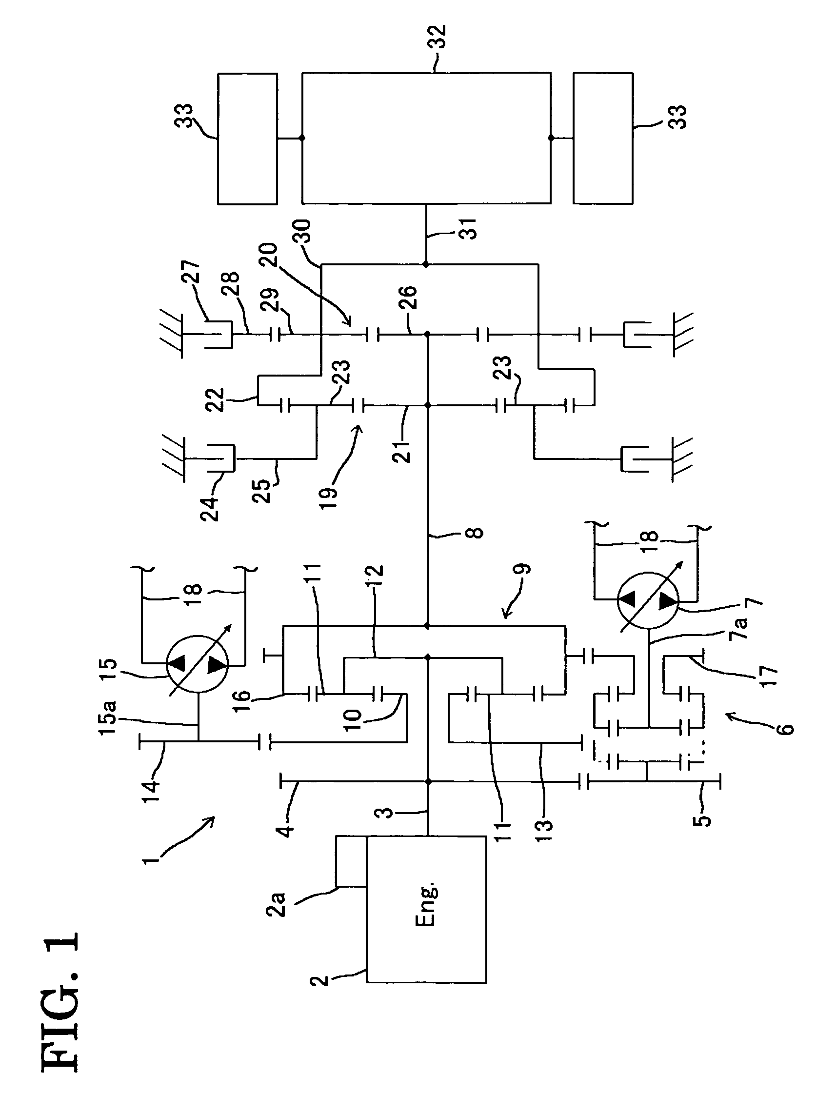
[0046]FIG. 1 is a schematic structural diagram of a vehicle control system constructed according to an embodiment of the invention. While this embodiment is associated with a case where the invention is applied to the driving system of a track type vehicle such as a bulldozer, it is apparent that the invention is not limited to this.

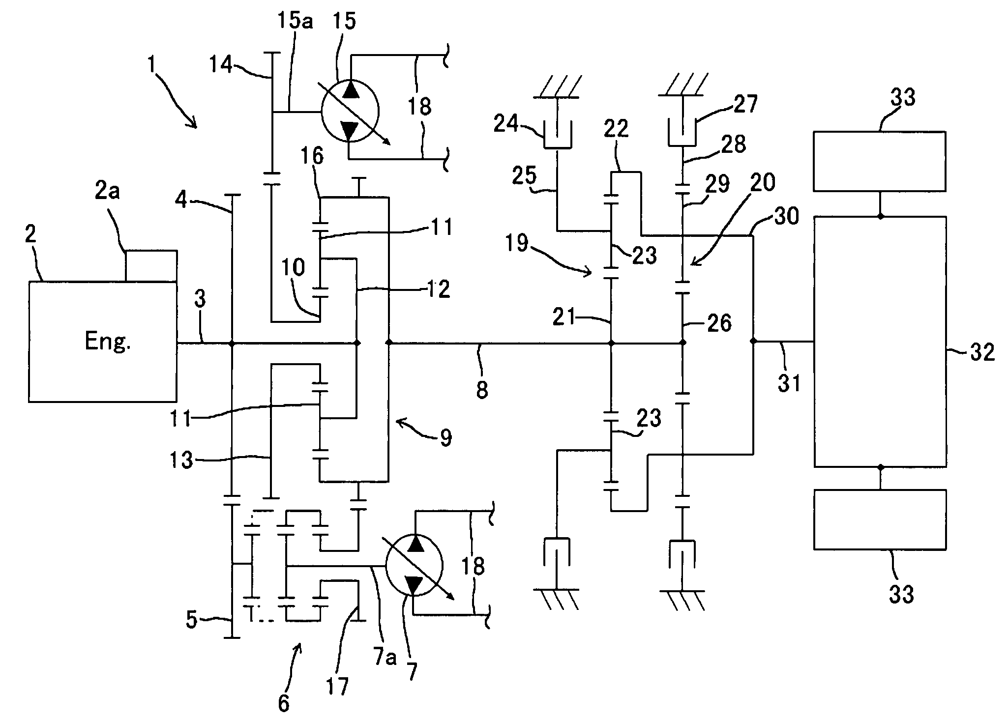
[0047]The vehicle control system of this embodiment has a diesel engine 2 and a hydro-mechanical transmission 1 (hereinafter referred to as “transmission 1”) designed to transmit the power of the engine 2 from its input shaft to its output shaft through a mechanical transmission unit and a hydrostatic transmission unit.

[0048]Mounted on the engine 2 is an accumulator (common rail) type fuel injection system 2a. This fuel injection system 2a itself is well known in the art and therefore is not illustra...


PUM


Abstract

A vehicle control system which is capable of performing a quick decelerating operation in all vehicle speed regions and setting a direct region where power from an engine is transmitted through a mechanical transmission unit only in a hydro-mechanical transmission. The vehicle control system includes an engine and a hydro-mechanical transmission and is designed to set a tractive force-vehicle speed characteristic corresponding to the direct region where power transmission from the input shaft to the intermediate output shaft of the hydro-mechanical transmission is done by the mechanical transmission unit alone in a specified engine speed region. An engine control system controls the engine and a decelerator outputs a deceleration command according to an operating amount thereof. The engine control system controls the engine to reduce engine output torque corresponding to a specified engine speed region in response to the deceleration command.

Description

TECHNICAL FIELD[0001]The present invention relates to a vehicle control system adapted for use in a work vehicle such as a bulldozer.BACKGROUND ART[0002]There have been known vehicle control systems having an engine and a hydro-mechanical transmission (HMT) which transmits engine power from an input shaft to an output shaft through a mechanical transmission unit and a hydrostatic transmission unit (e.g., Japanese Patent Kokoku Publication No. 62-31660). Since mechanical power can be transmitted with high efficiency, the transmission (HMT) provided for this vehicle control system is designed to convert only part of mechanical power into hydraulic power, so that it can achieve high transmission efficiency. Such a transmission is considered to be an ideal transmission for vehicles subjected to wide load variations such as bulldozers and wheel loaders and is, in fact, employed in some vehicles.[0003]In a typical hydro-mechanical transmission (HMT), variable speed characteristics are ach...

Claims


Application Information

Patent Timeline
Patent Type & Authority Patents(United States)
IPC IPC(8): B60W10/04B60W10/06F02D29/00F02D11/10F02D29/02F02D29/04F02D41/02F02D41/12F16D48/12F16H47/04
CPCB60K41/04B60W10/06B60W10/115F16H47/04F16H61/46F16H61/468Y10T477/688B60W2710/0661B60W2710/0672B60W2710/1055B60W2720/10F16H2037/0866F16H2037/088F16H2200/2005Y10T477/679Y10T477/675B60K2741/04B60W30/18B60W2300/17
Inventor FUNATO, MASAHIROOKADA, TOSHIKAZUYAMAMOTO, SHIGERUNAKAGAWA, TOMOHIRO
Owner KOMATSU LTD
Why Eureka
Try Eureka