Power supply apparatus including fuel cell and capacitor, and operation method thereof
a technology of power supply apparatus and capacitor, which is applied in the direction of battery/fuel cell control arrangement, secondary cell servicing/maintenance, electrochemical generator, etc., can solve the problems of reducing the energy efficiency of the fuel cell system as a whole, increasing the electric power consumed by the auxiliary device relative to the total power generation, etc., to prevent the reduction of the energy efficiency of the power supply apparatus and the drop of the energy efficiency of the fuel cell system
- Summary
- Abstract
- Description
- Claims
- Application Information
AI Technical Summary
Benefits of technology
Problems solved by technology
Method used
Image
Examples
third embodiment
F.
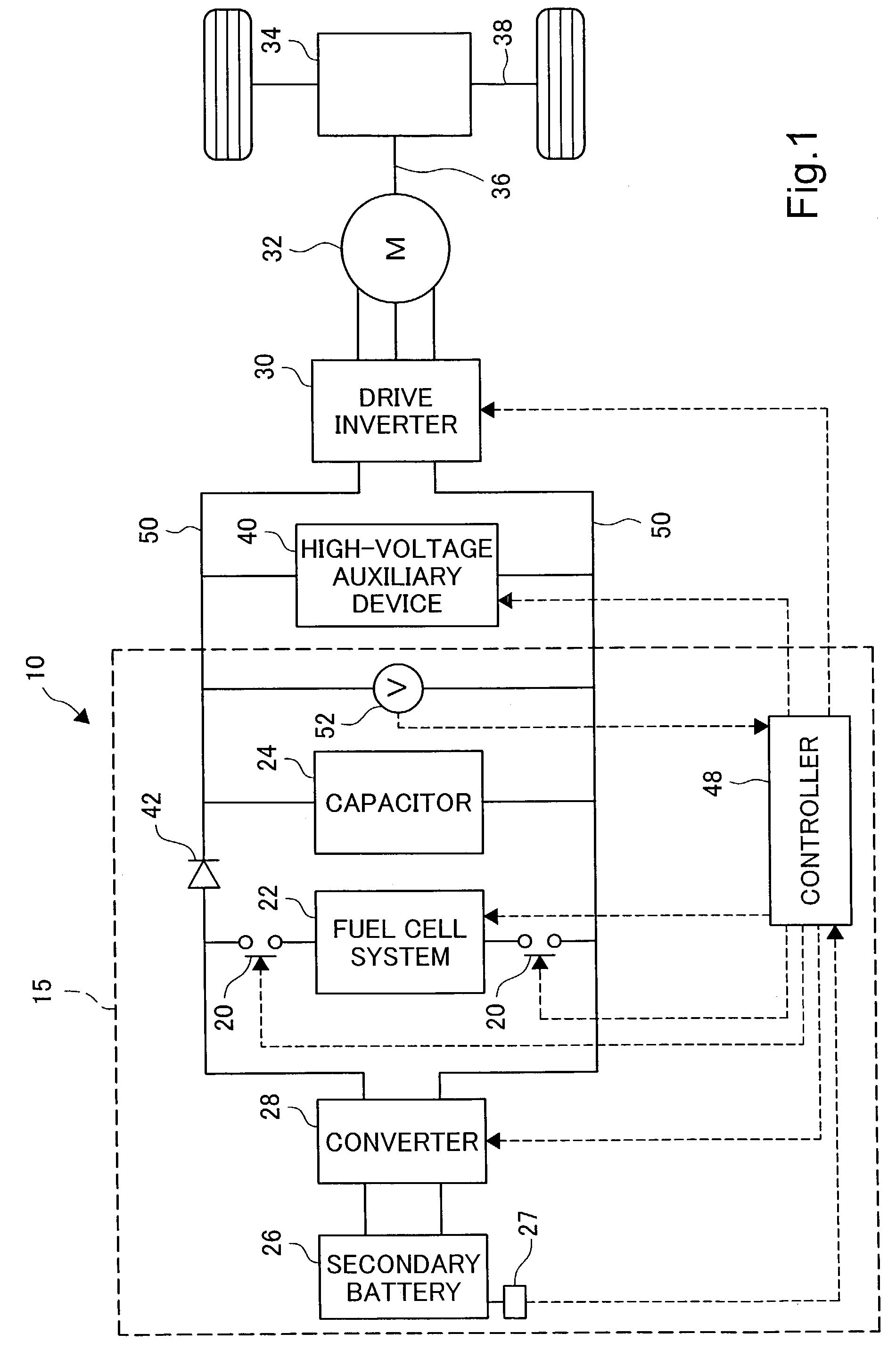
[0072]In the first and second embodiments described above, the reference voltage value V0 used for the comparison with the output voltage (capacitor voltage) VC detected by the voltmeter 52 when the determination regarding opening or closing of the switches 20 was a single value, but a different configuration may be used. As a third embodiment, a control method will be described below in which different values are used as the reference voltage values employed when determining the timing for switching between the normal operating mode and the FC suspend mode. The reference voltage used for determining the timing of closing the switches 20 may be adjusted. The third embodiment will be described based on the electric vehicle 110 of the second embodiment, but it may also be applied to the first embodiment.
[0073]FIG. 8 shows two different reference voltages for use in the determination of switching between the intermittent driving mode and the FC suspend mode. In this embodiment, the f...
fourth embodiment
G.
[0091]The fourth embodiment of the present invention is related to the operation to start the fuel cell 60 in the regenerative operating mode. The regenerative operating mode is an operating mode in which, by using a drive motor as a power generating device during braking (i.e., when the driver is stepping on the brake while the vehicle is running), the kinetic energy of the vehicle is converted into electrical energy. The control in the fourth embodiment is carried out in order to prevent an excessive rise in the capacitor voltage when this electrical energy is accumulated in the capacitor. The description of the fourth embodiment below will be based on the same electric vehicle 110 used in the description of the second and third embodiments, but it is also applicable to the vehicle of the first embodiment.
[0092]FIG. 11 is a flow chart showing the regeneration operation determination routine executed when a braking instruction is issued (i.e., when the brake is being stepped on)....
PUM
 Abstract
Description
Claims
Application Information
 - R&D
- Intellectual Property
- Life Sciences
- Materials
- Tech Scout
- Unparalleled Data Quality
- Higher Quality Content
- 60% Fewer Hallucinations
Browse by: Latest US Patents, China's latest patents, Technical Efficacy Thesaurus, Application Domain, Technology Topic, Popular Technical Reports.
© 2025 PatSnap. All rights reserved.Legal|Privacy policy|Modern Slavery Act Transparency Statement|Sitemap|About US| Contact US: help@patsnap.com


