
System and method for receiving OFDM signal

a technology of ad converter and ad converter, which is applied in the field of system and method for receiving ofdm signal, can solve the problems of inability to reduce the power consumed in the ad converter or the circuit that executes digital signal processing, and the inability to adapt to mobile communication apparatuses

Inactive Publication Date: 2007-03-27
KK TOSHIBA
View PDF7 Cites 57 Cited by
  • Summary
  • Abstract
  • Description
  • Claims
  • Application Information

AI Technical Summary

Benefits of technology

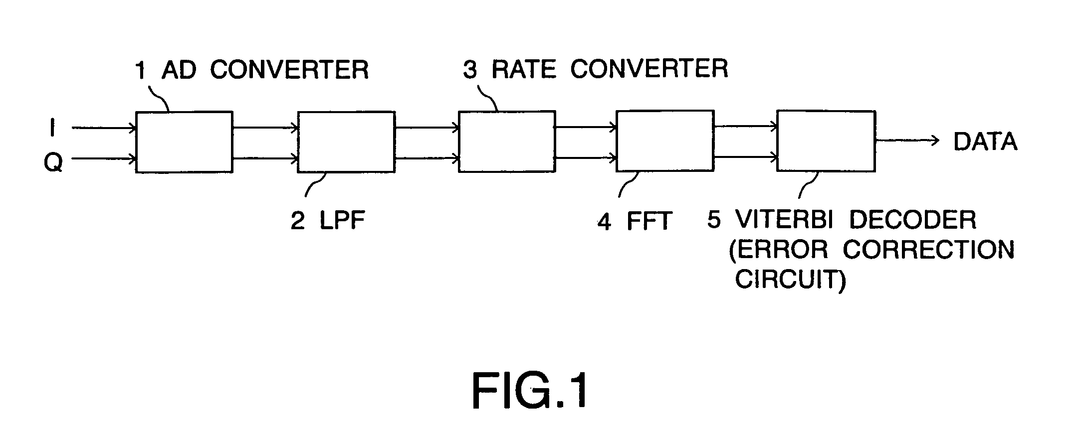
[0011]An AD converter samples a received signal at a first sampling rate. A low pass filter removes noise from a signal outputted from said AD converter. A rate converter extracts data from a signal outputted from said low pass filter at a second sampling rate. An OFDM signal decoding circuit converts and decodes a signal outputted from said rate converter from a time domain to a frequency domain. An error correction circuit corrects errors of a signal outputted from said OFDM signal decoding circuit. The low pass filter is a filter capable of varying a frequency characteristic in response to said first sampling rate.
[0013]An AD converter samples a received signal at a first sampling rate. A low pass filter removes noise from a signal outputted from said AD converter. A rate converter extracts data from a signal outputted from said low pass filter at a second sampling rate. An OFDM signal decoding circuit converts and decodes a signal outputted from said rate converter from a time domain to a frequency domain. An error correction circuit corrects errors of a signal outputted from said OFDM signal decoding circuit. A modulation system detecting circuit detecting a modulation system of said received signal. An operational unit of said AD converter changes the number of sampling bits in response to the modulation system detected in said modulation system detecting circuit.

Problems solved by technology

However, since power consumption is increased in such an AD converter, this AD converter is not suitable for a mobile communication apparatus.
Therefore, even if the data transmission rate is lowered to change the modulation system, the power consumed in the AD converter or the circuit that executes the digital signal processing has not been able to be reduced.

Method used


Image

  • System and method for receiving OFDM signal
  • System and method for receiving OFDM signal
  • System and method for receiving OFDM signal

Examples


first embodiment

(First Embodiment)

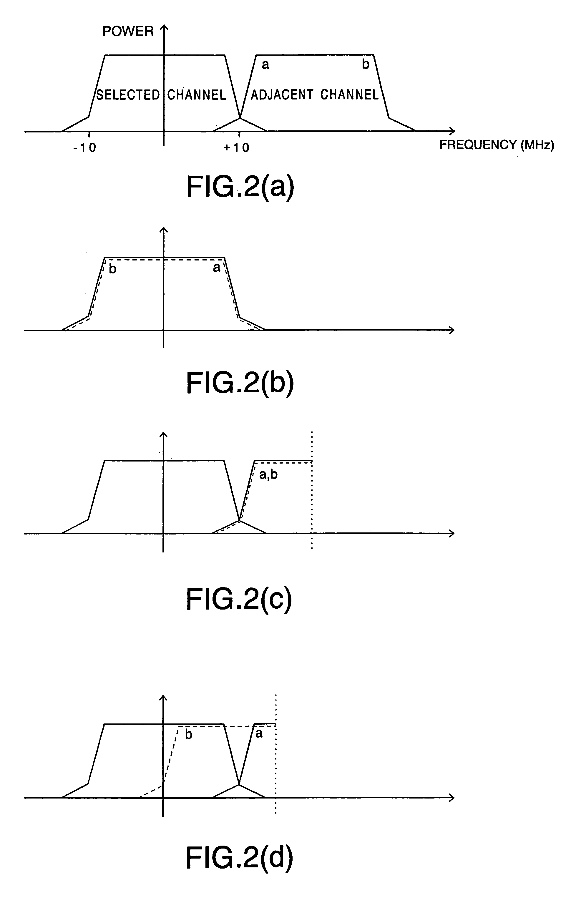
[0027]Wireless channels in the 5 GHz band, which are for use in the wireless LAN, are set at an interval of 20 MHz on the premise that signals subjected to (OFDM modulation are used therefor. An effective bandwidth per one channel is about 17 MHz, and there is a buffering band of about 3 MHz between one channel and a channel adjacent thereto. Therefore, when using a channel selection filter mounted with an RF or an IF, it is difficult to significantly remove a signal component of the adjacent channel. A base band signal converted from analog to digital and sampled. Then, a low pass filter (hereinafter referred to as “LPF”) by digital signal processing is realized, and the signal component of the adjacent channel is removed.

[0028]FIG. 1 is a block diagram of a system for receiving an OFDM signal according to a first embodiment. The system for receiving an OFDM signal of this embodiment includes an AD converter 1 which samples orthogonal signals of I and Q as digital...

second embodiment

(Second Embodiment)

[0045]In the wireless LAN using the OFDM modulation system in the 5 GHz band, there are standards such as IEEE 802.11a, HIPERLAN Type 2, and the like. Moreover, there are seven data transmission rates, including 6, 9, 12, 18, 27, 36 and 54 Mbps, and there are four subcarrier modulation systems, including BPSK, QPSK, 16 QAM and 64 QAM.

[0046]In the system for receiving an OFDM signal, the number of bits required for the operation differs depending on the modulation system for each subcarrier. For example, in order to deal with the 64 QAM modulation for use at the time of 54 Mbps as the maximum transmission rate, the AD converter samples 12-bit. Meanwhile, in the BSPK modulation for use at the time of minimum transmission rate of 6 Mbps, 8-bit sampling data is sufficient. Similarly, 10-bit sampling data is sufficient for 16 QAM modulation, and 8-bit sampling data is sufficient for QPSK modulation.

[0047]

Table 1 shows a relation between the number of bits and thetransm...

third embodiment

(Third Embodiment)

[0064]A block diagram of a system for receiving an OFDM signal according to a third embodiment is the same as FIG. 6 shown in the second embodiment. Modulation system detecting circuit 6 in the third embodiment detects a modulation system of a received signal, and in response to the detected modulation system, switches the sampling rate of the AD converter 1. For example, BPSK and QPSK are operated at the sampling rate of 30 MSPS, and 16 QAM and 64 QAM are operated at the sampling rate of 40 MSPS.

[0065]In this embodiment, since the sampling rate is switched in response to the transmission rate (modulation system), the modulation system at the slow transmission rate is operated at a low sampling rate, and thus the power consumption can be reduced. Moreover, the modulation system with a rapid transmission rate is operated at a high sampling rate, and thus the signal can be decoded stably without a large noise influence.

[0066]With regard to the AD converter 1 in this ...


PUM


Abstract

A system for receiving an OFDM signal. An AD converter samples a received signal at a first sampling rate. A low pass filter removes noise from a signal outputted from the AD converter. A rate converter extracts data from a signal outputted from the low pass filter at a second sampling rate. An OFDM signal decoding circuit converts and decodes a signal outputted from the rate converter from a time domain to a frequency domain. An error correction circuit corrects errors of a signal outputted from the OFDM signal decoding circuit. The low pass filter varies its frequency characteristic in response to said first sampling rate.

Description

CROSS REFERENCE TO RELATED APPLICATION[0001]This application claims the benefit of priority from prior Japanese Patent Application No. 2001-322985, filed on Oct. 22, 2001; the entire contents of which are incorporated herein by reference.BACKGROUND OF THE INVENTION[0002]A wireless LAN (local area network) in the 5 GHZ band is premised on the use of an OFDM (orthogonal frequency division multiplexing) modulation system. The OFDM modulation system processes received signals as described below. A received OFDM signal is sampled as a digital signal (data) in an AD converter. In the sampled data, a frequency component of a channel adjacent to the data is removed in a low pass filter by digital signal processing. Then, the data is subjected to extraction processing at a required sampling rate in a rate converter. The data subjected to extraction processing is subjected to Fourier conversion in an OFDM signal decoding circuit. Then, errors of the data converted in a Viterbi decoder is corr...

Claims


Application Information

Patent Timeline
Patent Type & Authority Patents(United States)
IPC IPC(8): H04L27/28H04L25/03H04J11/00H04L27/26
CPCH04L27/2647H04L25/03828H04J11/00
Inventor SAITO, TOSHITADA
Owner KK TOSHIBA
Learn More