Air guide for cooling a vehicle brake assembly

a technology for brake assemblies and air guides, which is applied to the brake discs, brakes with fluid actuation, roofs, etc., can solve the problems of brake assembly heating, brake assembly damage, and frictional engagement of brake pads against the rotor generating enormous heat energy, so as to prolong the life of the brake assembly, improve the performance, and reduce the temperature of the brake assembly

Inactive Publication Date: 2007-04-03
HONDA MOTOR CO LTD
View PDF31 Cites 23 Cited by
  • Summary
  • Abstract
  • Description
  • Claims
  • Application Information

AI Technical Summary

Benefits of technology

[0010]The present invention decreases the temperature of the brake assembly before, during, and after mild or hard braking, and thereby improves the performance and extends the life of the brake assembly. The present invention is directed toward a device for providing effective cooling for brake rotors that utilizes the ram air affect at the front of a vehicle.

Problems solved by technology

While this common type of braking device effectively slows the vehicle's movement, the frictional engagement of the brake pads against the rotor generates an enormous amount of heat energy.
This heat energy causes heating of the brake assembly.
If this heat is not properly dissipated from the brake assembly, damage to the brake assembly can result.
For example, excessive brake heat can cause brake jutter and premature brake deterioration.
While this device does provide enhanced cooling characteristics of the brake assembly, it has some drawbacks.
However, this known channeling device does not pressurize the air, but rather only diverts air toward and across the vehicle brakes.
Furthermore, placement of the channeling device tends to reduce the amount of room available for other components.
One drawback of this cooling system is that relatively higher-pressure air, which would provide more efficient cooling, cannot be provided to the brake assembly.

Method used


Image

  • Air guide for cooling a vehicle brake assembly
  • Air guide for cooling a vehicle brake assembly
  • Air guide for cooling a vehicle brake assembly

Examples


Embodiment Construction

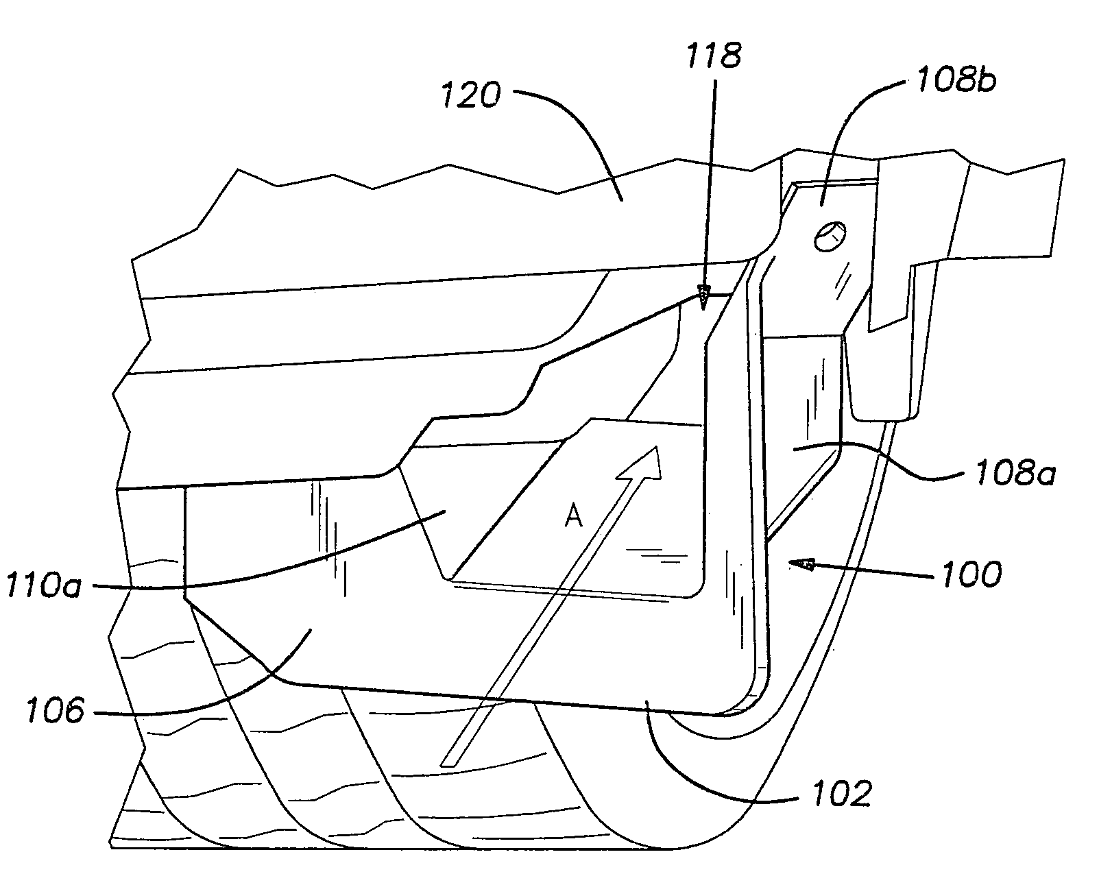
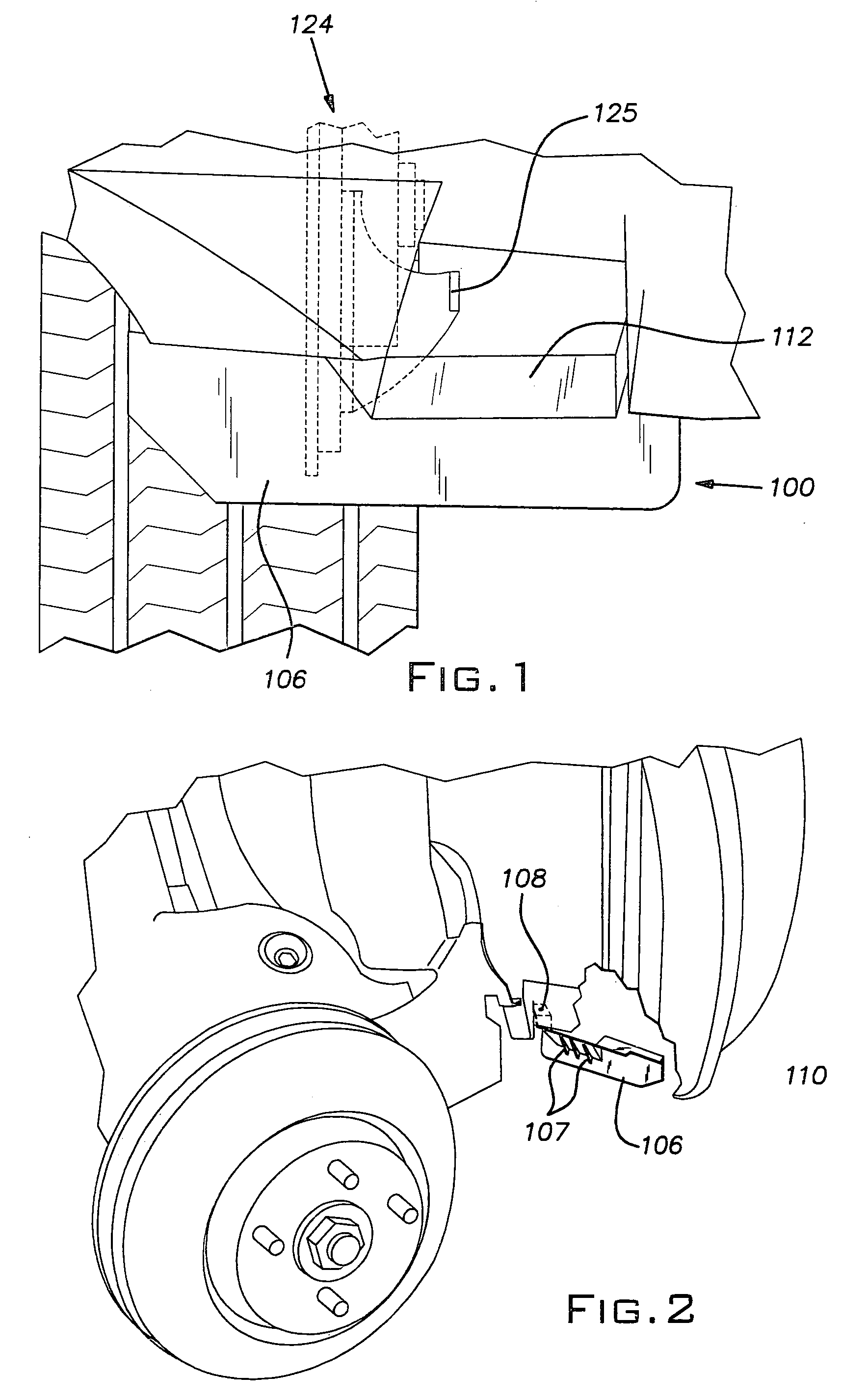
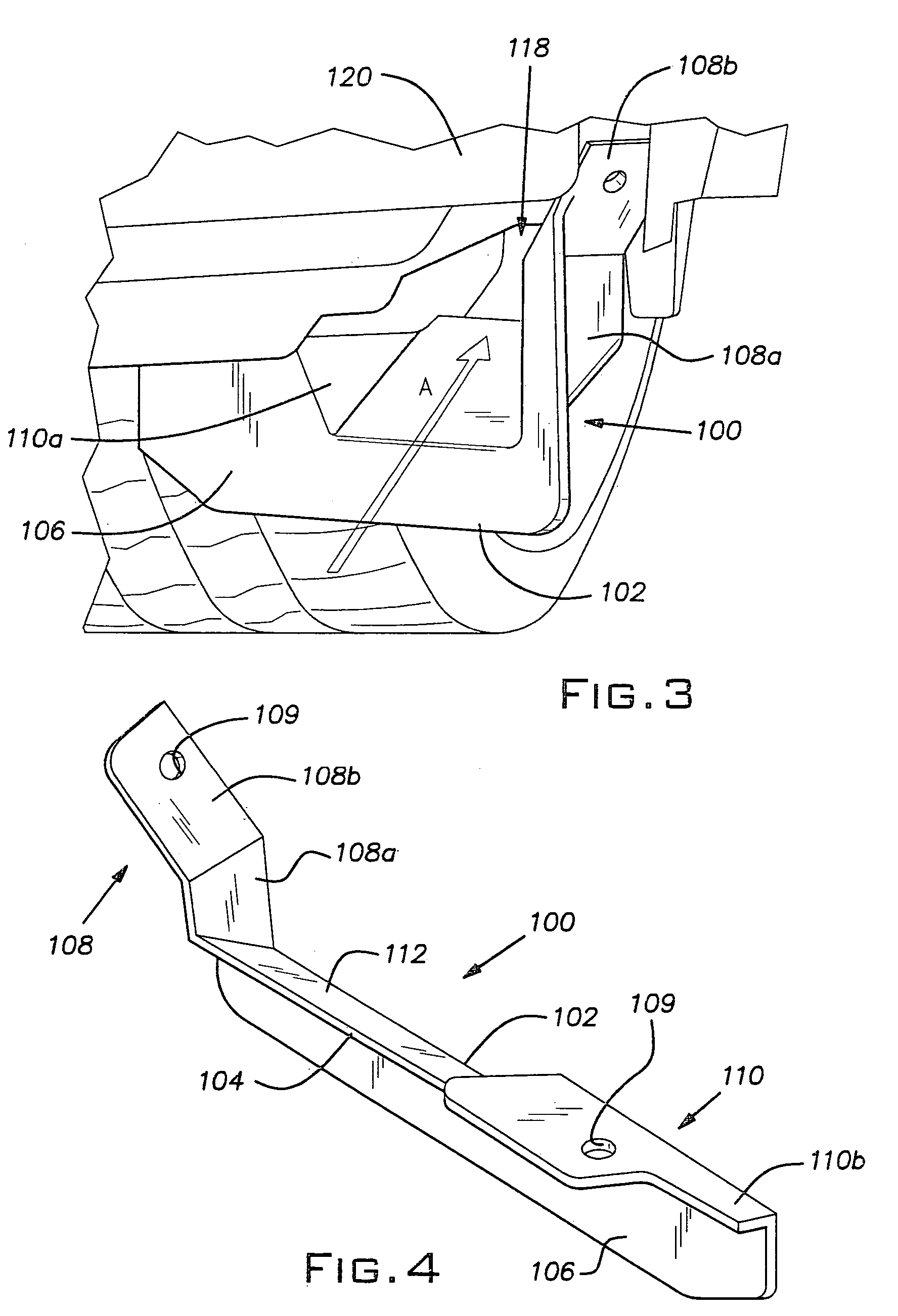
[0020]With reference to FIGS. 1–6, an air guide 100 according to the invention is shown to include a proximal end 102 and a distal end 104. The proximal end 102 faces forward toward the front of the vehicle 101, and the distal end 104 faces rearward toward the associated vehicle brake assembly 124. A front wall 106 is disposed at the proximal end 102 of the air guide 100 and is generally U-shaped, as shown best in FIG. 4. First and second lateral support wings 108, 110 extend laterally and upwardly from the front wall 106.

[0021]An air funneling wall 112 is secured to the front wall 106 and to the first and second lateral support wings 108, 110. The air funneling wall 112 extends distally and upwardly from the front wall 106, and defines the distal end 104 of the air guide 100. A forward end of the air funneling wall 112 is secured to the front wall 106 while lateral ends of the air funneling wall 112 are secured to the first and second lateral support wings 108, 110, respectively. A...


PUM


Abstract

A brake cooling system that directs cooling air to a vehicle brake assembly. The cooling system includes an air guide that, during operation of the vehicle, receives air, pressurizes air, and directs pressurized air to the brake assembly. The air guide cooperates with a support structure, such as a wheel well liner, provided by the vehicle to define an air passageway that is gradually reduced in cross-section toward the distal end of the air guide so as to transform a relatively low pressure incoming air stream into a relatively higher pressure outgoing air stream. The outgoing air stream is focused on the brake assembly to thereby cool the brake assembly.

Description

BACKGROUND OF THE INVENTION[0001]1. Field of the Invention[0002]The present invention relates to a brake cooling system, and more particularly, to an air guide that directs pressurized cooling air to a vehicle brake assembly.[0003]2. Description of Related Art[0004]Brake assemblies are used to slow and stop vehicle movement. Brake assemblies often include a rotor attached to the wheels of a vehicle, and calipers positioned in a clamping arrangement about surfaces of the rotor. When slowing or stopping is initiated, hydraulic pressure from a master cylinder is supplied to the caliper, thereby causing the brake pads carried on the caliper to frictionally engage and clamp the rotor and thereby slowing rotation of the rotor and the associated wheel.[0005]While this common type of braking device effectively slows the vehicle's movement, the frictional engagement of the brake pads against the rotor generates an enormous amount of heat energy. This heat energy causes heating of the brake a...

Claims


Application Information

Patent Timeline
Patent Type & Authority Patents(United States)
IPC IPC(8): B62D35/00F16D65/78
CPCF16D65/78
Inventor WILSON, DEREKCRICHLEY, SHAWNMISSIG, MICHAEL
Owner HONDA MOTOR CO LTD
Why Eureka
Try Eureka