Compact low NOx gas burner apparatus and methods
a burner and low-cost technology, applied in lighting and heating apparatus, combustion types, combustion using lump and pulverizing fuel, etc., can solve the problems of low turn down ratio and long flame length, and achieve the effect of short flame length and high turn down ratio
- Summary
- Abstract
- Description
- Claims
- Application Information
AI Technical Summary
Benefits of technology
Problems solved by technology
Method used
Image
Examples
example 1
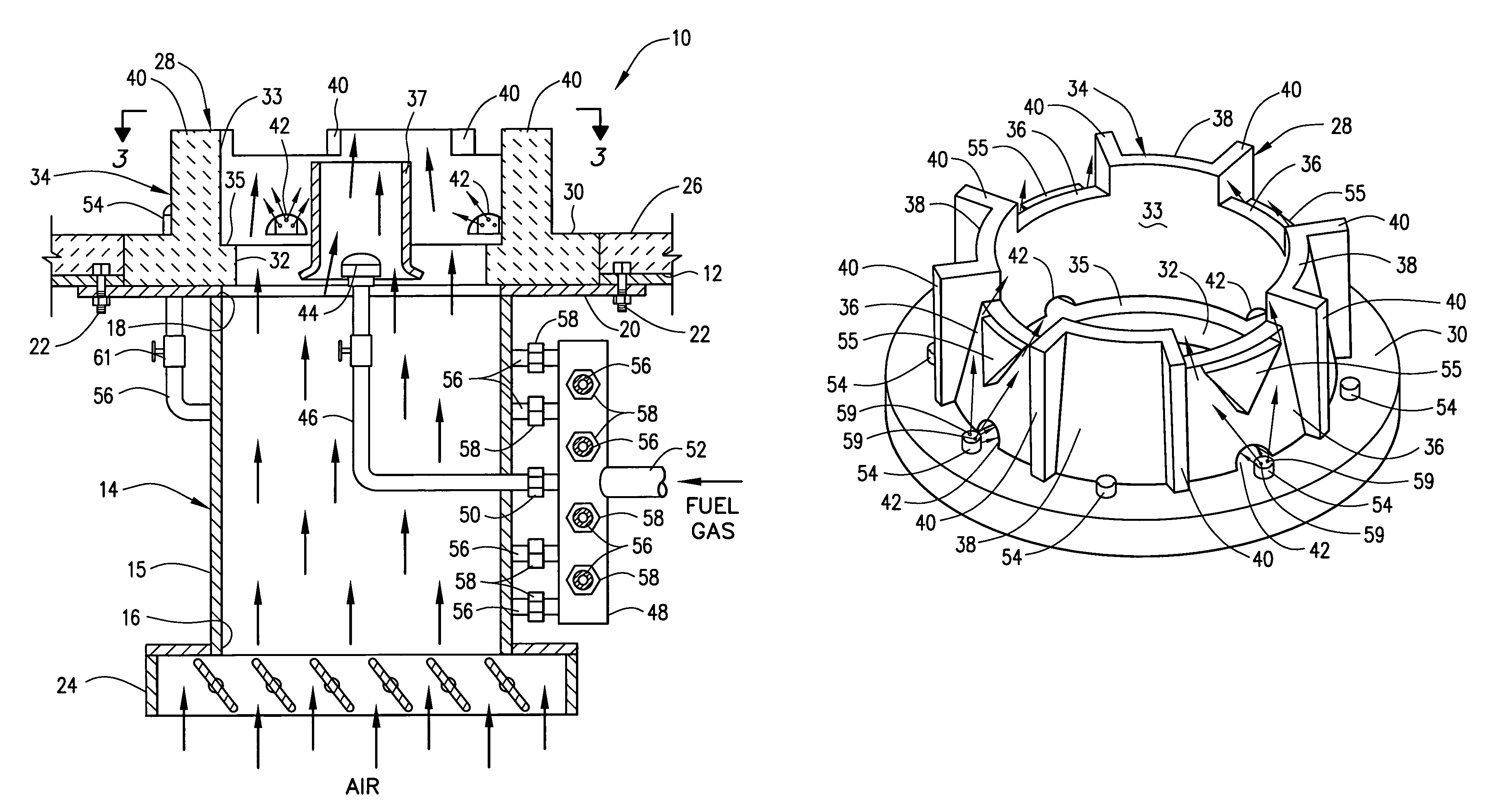
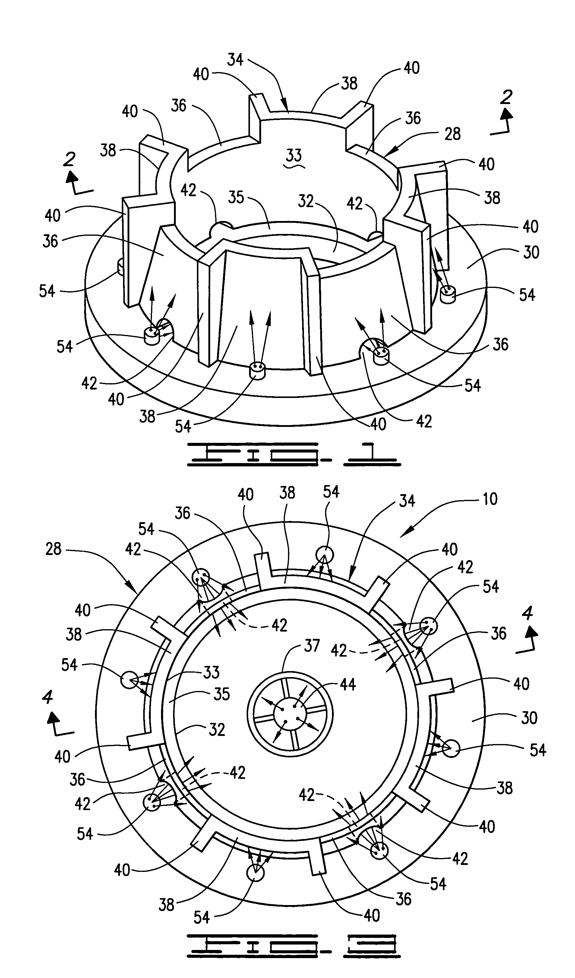
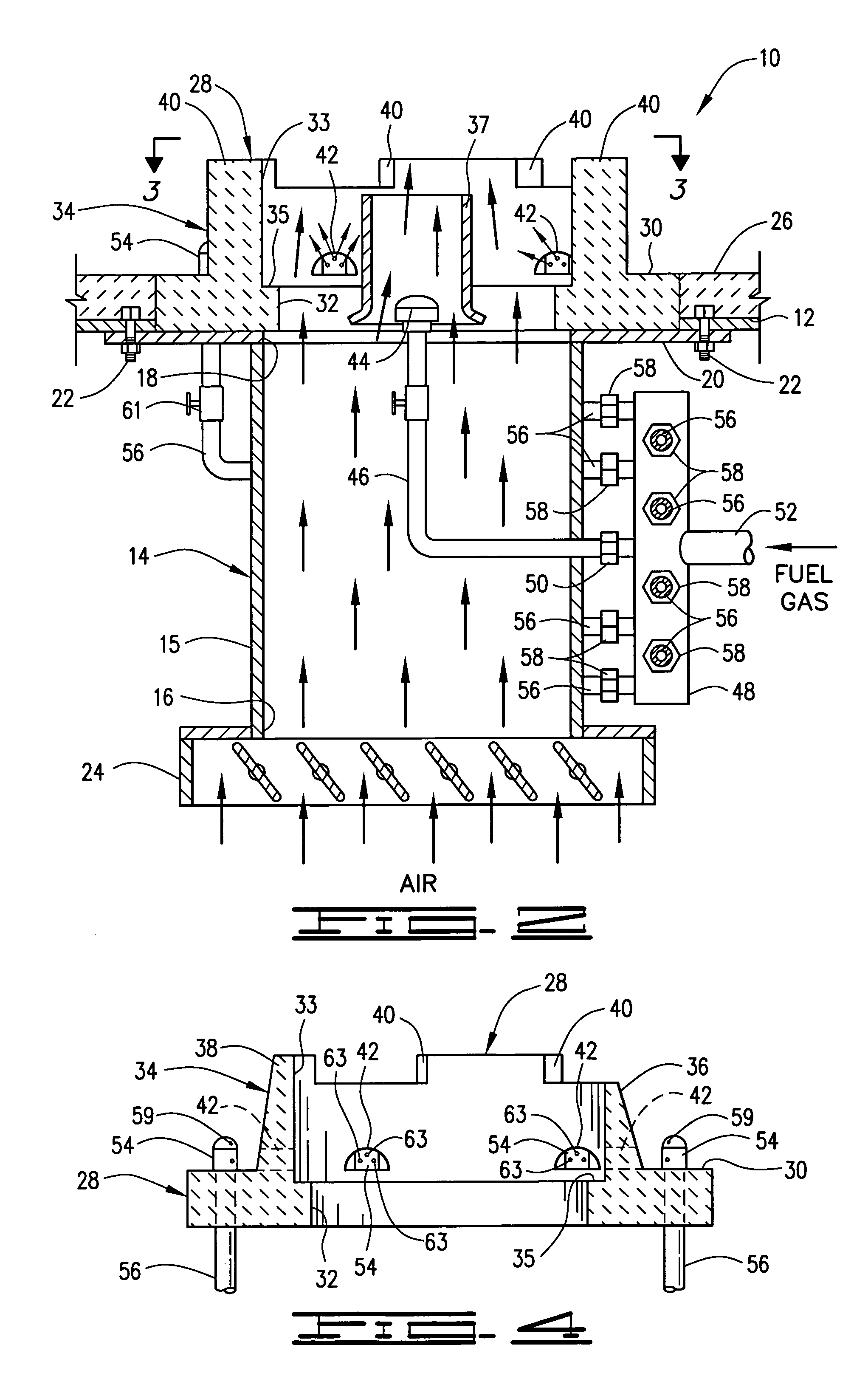
[0056]A burner apparatus 10 designed for a heat release of 8,000,000 BTU per hour by burning natural gas having a caloric value of 913 BTU / SCF was fired into a furnace space. Pressurized fuel gas was supplied to the manifold 48 of the burner 10 at a pressure of about 33 psig and a flow rate of about 8765 SCF / hour. A 20% by volume portion of the fuel gas (1753 SCF / hour) was used as primary fuel gas and was discharged within the opening 32 and wall 34 of the burner tile 28 by the fuel gas discharge nozzle 44 and by the fuel gas discharge nozzles 54 positioned adjacent to the openings 42 in the wall 40 of the burner tile 28. The remaining portion of the fuel gas, i.e., the secondary portion (at a rate of 7012 SCF / hour) was discharged into the furnace space by the nozzles 54 in separate fuel gas streams mixed with flue gases.
[0057]The rate of air introduced into the furnace space by way of the air register 24, the housing 14 and the burner tile 28 was at least 15% in excess of the stoic...
example 2
[0058]In order to see the flame pattern produced by the burner apparatus 10 when operated as described in Example 1 above, a computer simulation program was utilized. The software used was obtained from Fluent Inc. of Lebanon, N.H. The design of the burner was reconstructed in the simulation program in full three dimensional detail including all important features such as tile facets, fuel gas port drillings, flame holder tile ledge and complete air plenum configuration.
[0059]A three dimensional model of the furnace in which the burner apparatus was tested was then prepared and the burner model was mounted in the furnace model exactly like the test burner and furnace utilized in Example 1 except that the air entered the housing from the side instead of the bottom. The flow spaces in the burner model were divided into small volumes using the finite volume method and boundary conditions were applied, e.g., fuel pressure, flow rates, etc. at the entrances of the burner model. The softw...
PUM
 Abstract
Description
Claims
Application Information
 - R&D
- Intellectual Property
- Life Sciences
- Materials
- Tech Scout
- Unparalleled Data Quality
- Higher Quality Content
- 60% Fewer Hallucinations
Browse by: Latest US Patents, China's latest patents, Technical Efficacy Thesaurus, Application Domain, Technology Topic, Popular Technical Reports.
© 2025 PatSnap. All rights reserved.Legal|Privacy policy|Modern Slavery Act Transparency Statement|Sitemap|About US| Contact US: help@patsnap.com


