Switching power supply unit

Active Publication Date: 2007-04-03
TDK CORPARATION
View PDF17 Cites 39 Cited by
  • Summary
  • Abstract
  • Description
  • Claims
  • Application Information

AI Technical Summary

Benefits of technology

[0006]However, when the winding of the transformer is stacked in the sandwiched manner as above, since area of opposed regions between the primary windings and the secondary windings is increased, line capacitance between the primary windings and the secondary windings is increased. As a result, ringing having large amplitude is generated in an output AC voltage of the transformer by LC resonance due

Problems solved by technology

There has been a difficulty that when the ringing having the large amplitude is generated in this way, core loss in the t

Method used


Image

  • Switching power supply unit
  • Switching power supply unit
  • Switching power supply unit

Examples


first embodiment

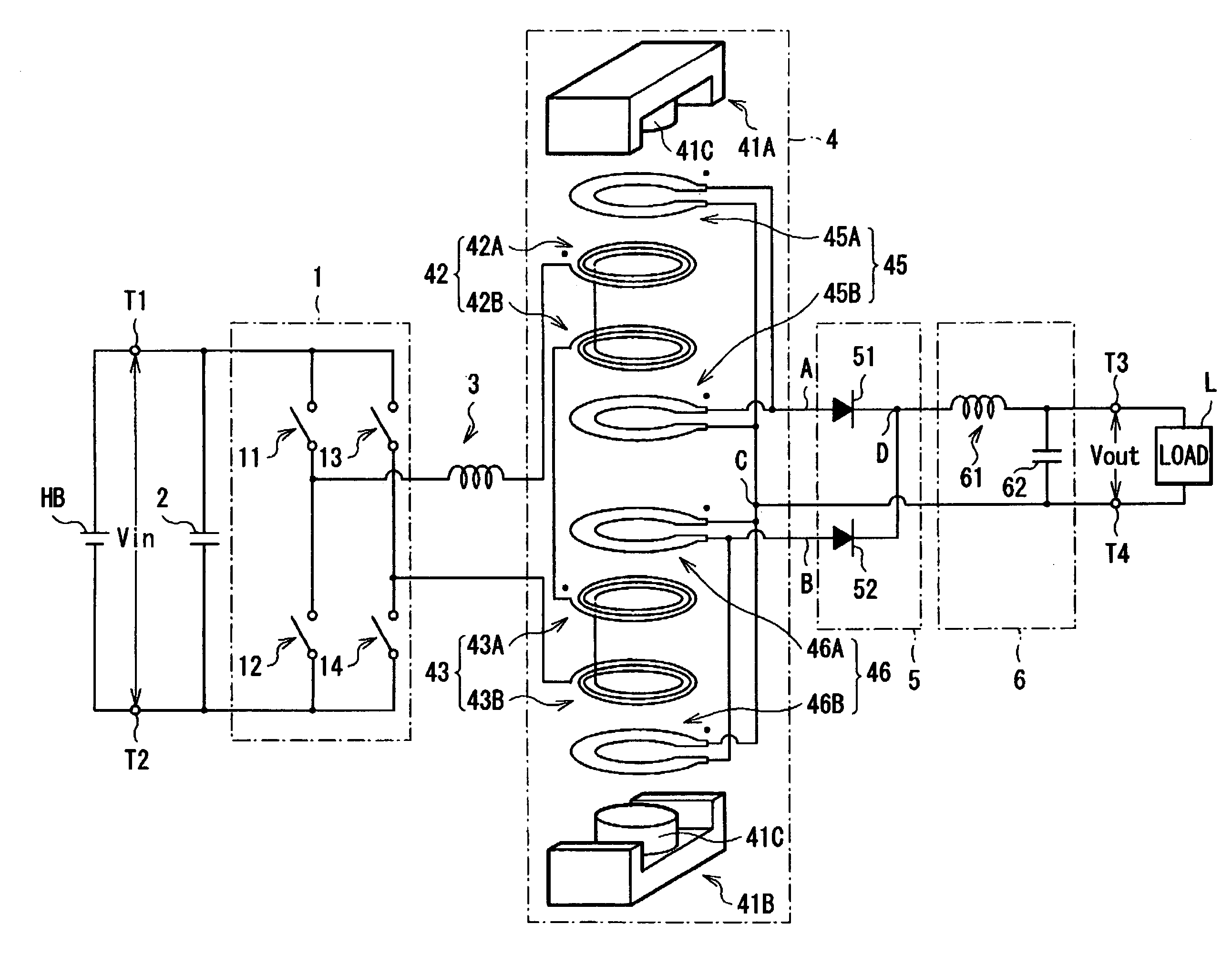
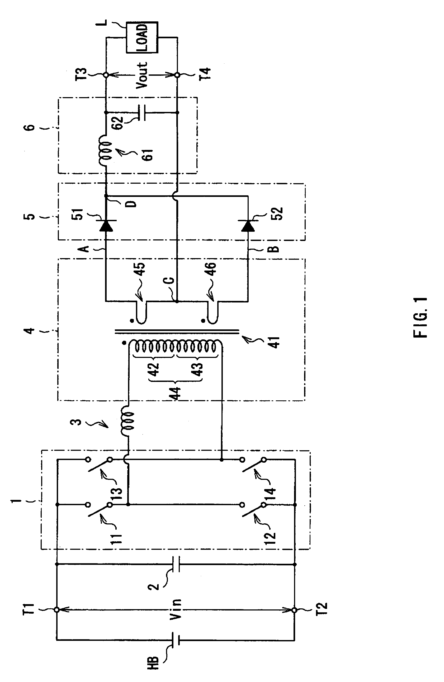
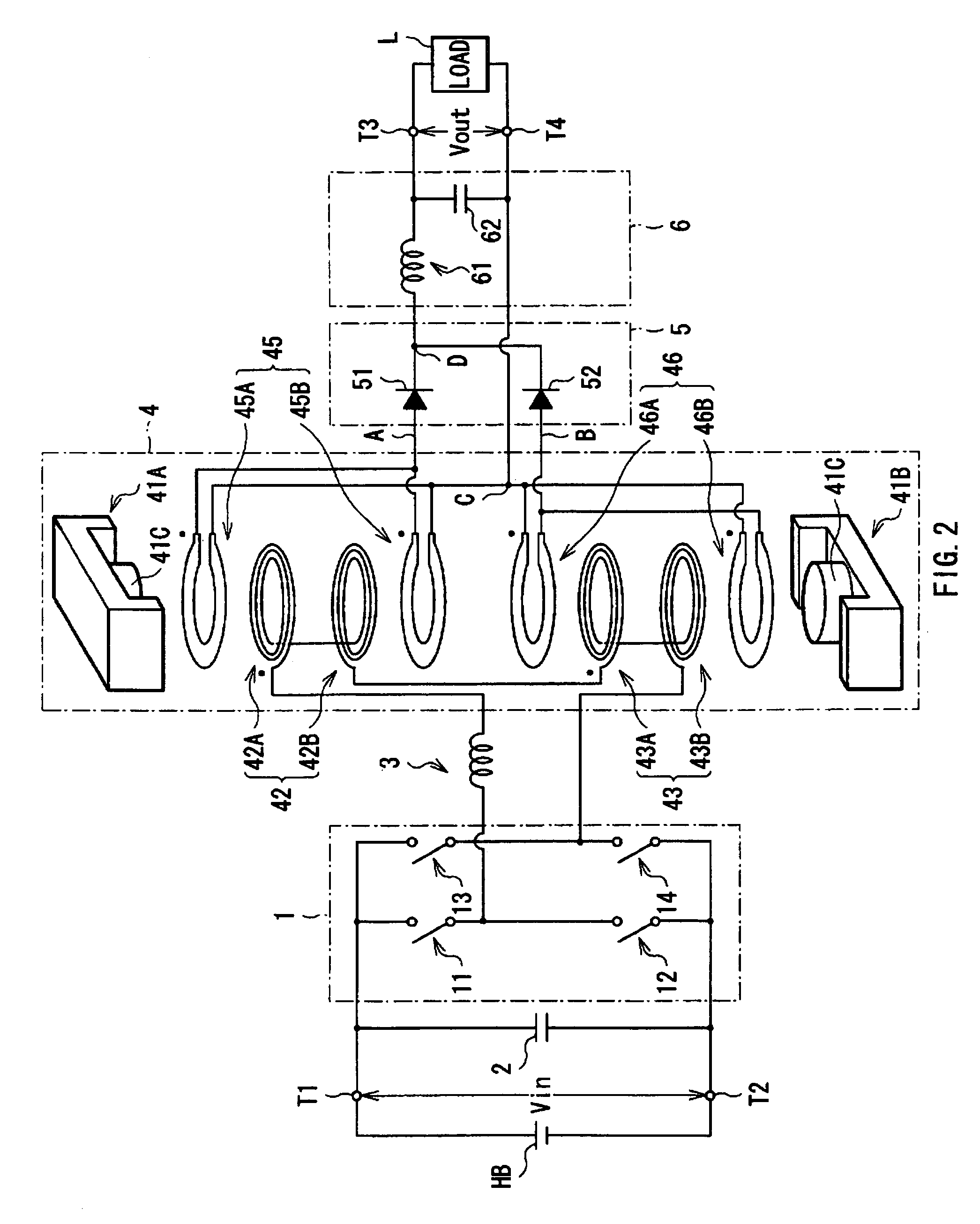
[0055]FIG. 1 shows a circuit configuration of a switching power supply unit according to a first embodiment of the invention. FIG. 2 shows a structure of a transformer in the switching power supply unit of FIG. 1 in an exploded manner. The switching power supply unit acts as a DC-to-DC converter converting a high DC input voltage Vin supplied from a high-voltage battery HB into a lower DC output voltage Vout, and supplying the DC output voltage to a load L, and is a switching power supply unit of which the secondary side is in a center tap type.

[0056]The switching power supply unit has an inverter circuit 1 (switching circuit) and a smoothing capacitor 2 provided between a primary-side high-voltage line L1H and a primary-side low-voltage line L1L; a transformer 4 configured to include a primary winding 44 including a primary winding 42 and a primary winding 43 connected in series to each other and a secondary winding 47 including a secondary winding 45 and a secondary winding 46 con...

second embodiment

[0096]FIG. 20 shows a circuit configuration of a switching power supply unit according to a second embodiment of the invention. FIG. 21 shows a structure of a transformer in the switching power supply unit of FIG. 20 in an exploded manner. The switching power supply unit is different from the first embodiment in a configuration of an inverter circuit 10, a connection relationship between the inverter circuit 10 and a transformer 40, and a configuration of the transformer 40. Thus, different points from the first embodiment are mainly described hereinafter, and configurations, operation, and effects common to the first embodiment are appropriately omitted to be described.

[0097]The inverter circuit 10 is a push-pull type switching circuit including two switching elements 15 and 16 connected in parallel, the switching elements 15 and 16 being driven according to a switching signal supplied from a control circuit (not shown).

[0098]The transformer 40 is configured by stacking respective ...


PUM


Abstract

A switching power supply unit is provided, in which core loss in a transformer or a level of heating due to AC resistance of the transformer can be reduced. A switching power supply unit has a transformer, an inverter circuit and a rectifier circuit. In a secondary side of the transformer, secondary wirings are connected to each other. In a primary side of the transformer, primary wirings are connected in series to each other, and connected to the inverter circuit to allow them to be driven in a time-divisional manner in phases opposite to each other in response to operation of the inverter circuit. The rectifier circuit has diodes connected to the secondary wirings to allow the secondary wirings to be driven in a time-divisional manner in phases opposite to each other in response to operation of the inverter circuit.

Description

BACKGROUND OF THE INVENTION[0001]1. Field of the Invention[0002]The present invention relates to a switching power supply unit transforming an input AC voltage obtained by switching an input DC voltage by a transformer, and outputting an output DC voltage obtained by rectifying and smoothing the transformed output AC voltage, and particularly relates to a switching power supply unit preferably applicable using high switching frequency.[0003]2. Description of the Related Art[0004]Hitherto, various types of switching power supply units have been proposed and provided for practical use. As one of the units, a type is given, in which an input DC voltage from a high-voltage battery is switched by switching operation of a switching circuit connected to an input winding of a transformer, an input AC voltage obtained by switching is inputted into the input winding of the transformer, and output AC voltage transformed by the transformer is drawn out from an output winding of the transformer,...

Claims


Application Information

Patent Timeline
IPC IPC(8): H01F17/00
CPCH02M3/335H02M7/003H01F30/10H01F2027/348
Inventor NAKAHORI, WATARU
Owner TDK CORPARATION
Why Eureka
Try Eureka