Impedance matching apparatus for a plasma chamber comprising two separate storage units and calculators

a plasma chamber and calculator technology, applied in the direction of transit-tube circuit elements, structural circuit elements, cathode-ray/electron beam tube circuit elements, etc., can solve the problems of insufficient matching accuracy of the matching circuit according to the cited document, inability to disregard the impedance matching performance of the impedance components,

Active Publication Date: 2007-04-03
DAIHEN CORP
View PDF5 Cites 59 Cited by
  • Summary
  • Abstract
  • Description
  • Claims
  • Application Information

AI Technical Summary

Benefits of technology

[0016]The present invention has been conceived in view of such situation, with an object to solve the foregoing problems.

Problems solved by technology

When handling a high-frequency wave, however, the circuit devices serving as the matching circuit of the impedance matching circuit 43 include not only the variable capacitors VC3, VC4 and the inductors L2, L3, but also stray capacitance components between those parts and the housing and inductance components of copper plates or waveguides connecting those parts, and influences such impedance components is unable to disregard on the impedance matching performance.
Accordingly, from a strict viewpoint, the impedance components such as the stray capacitance are not counted in the matching circuit, and hence the matching circuit is not designed to perform in consideration of the impedance components such as the stray capacitance.
As a result, the matching circuit according to the cited document fails to perform with sufficient accuracy, especially in a high-frequency region.
Therefore, the matching circuits including the impedance components such as the stray capacitance may have different characteristics depending on the internal structure of the matching apparatus, even though the matching circuits are constituted of the same variable capacitors VC3, VC4 and the inductors L2, L3, and hence may suffer from the problem of unequal matching accuracy among the apparatuses.

Method used


Image

  • Impedance matching apparatus for a plasma chamber comprising two separate storage units and calculators
  • Impedance matching apparatus for a plasma chamber comprising two separate storage units and calculators
  • Impedance matching apparatus for a plasma chamber comprising two separate storage units and calculators

Examples


first embodiment

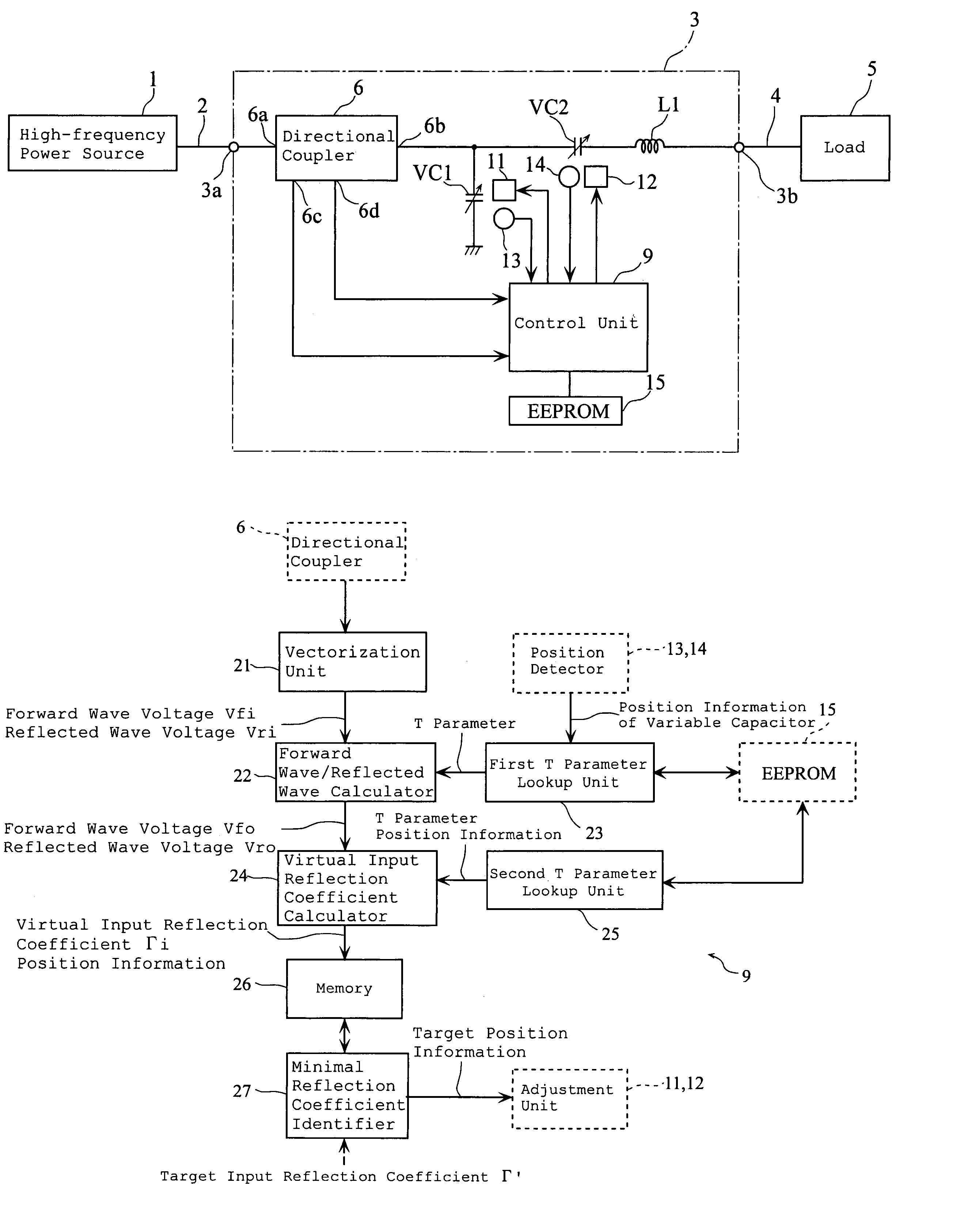
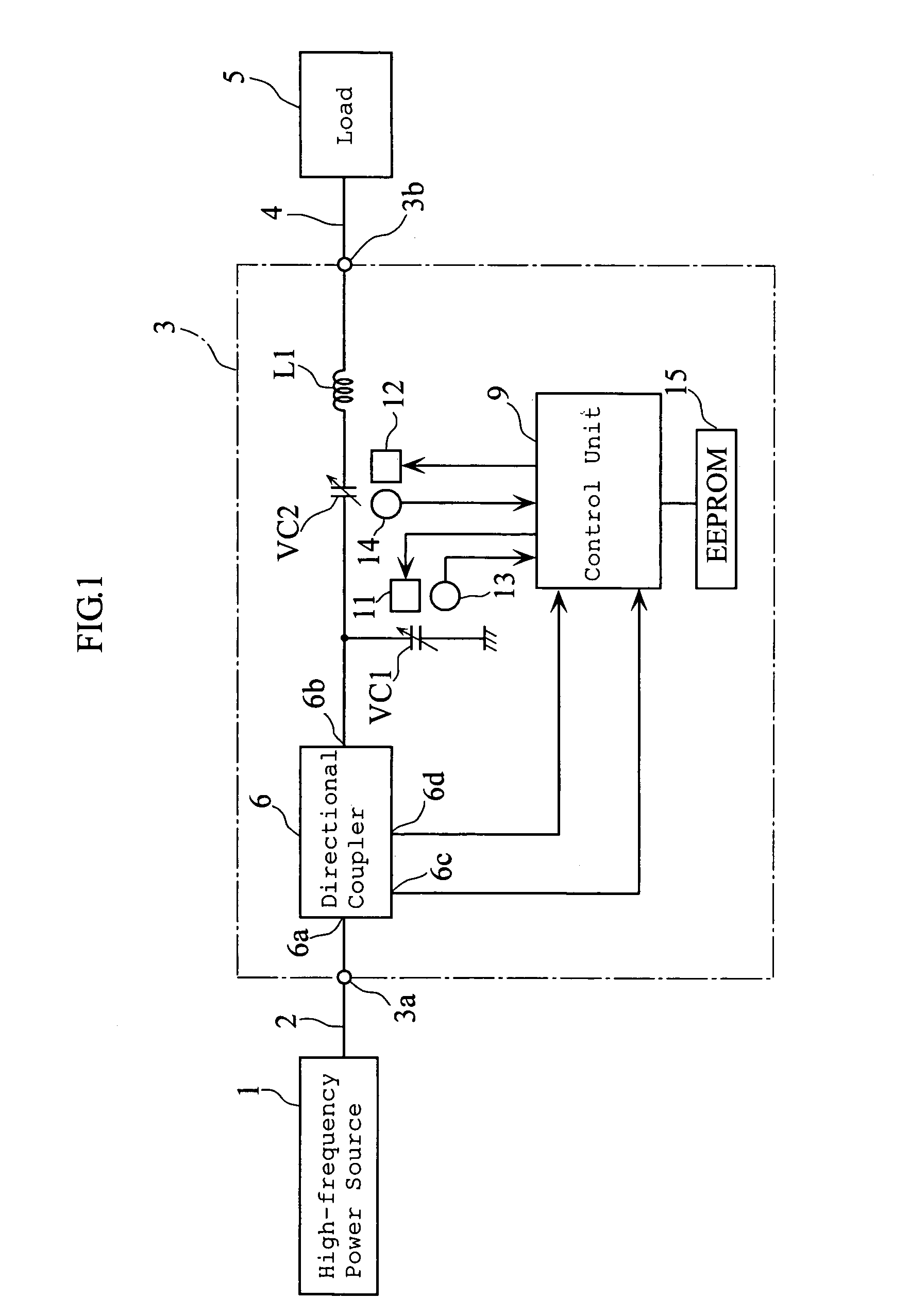
[0036]FIG. 1 is a block diagram showing a configuration of a high-frequency power supply system including an impedance matching apparatus according to the present invention, and a circuit diagram of the impedance matching apparatus.

[0037]The high-frequency power supply system supplies a high-frequency wave to an object to be processed such as a semiconductor wafer or a liquid crystal substrate, to thereby perform a processing such as plasma etching. The high-frequency power supply system includes a high-frequency power source 1, a transmission line 2, an impedance matching apparatus 3, a load connector 4 and a load 5 including a plasma processing apparatus (plasma process chamber).

[0038]The high-frequency power source 1 supplies a high-frequency power with a predetermined frequency (for instance, 13.56 MHz or 200 MHz) to the load 5. The high-frequency power source 1 is connected to the impedance matching apparatus 3 via the transmission line 2, which is for example a coaxial cable. ...

second embodiment

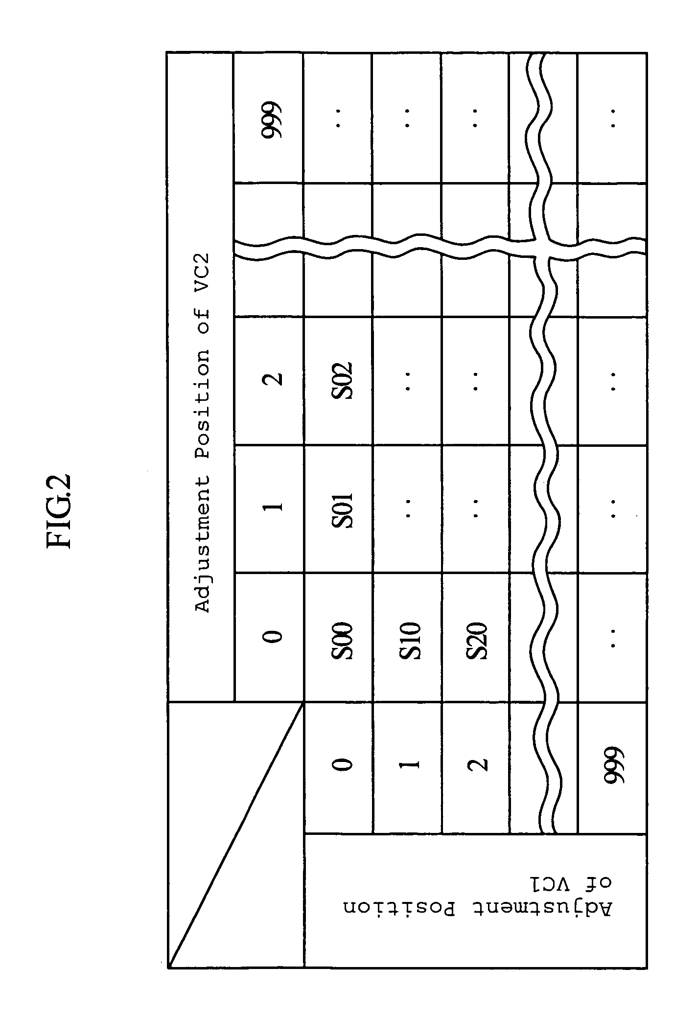
[0138]As described above, the impedance matching apparatus 3 is utilized as a transmission apparatus as a whole, so as to acquire the transmission characteristic of the transmission apparatus in a form of the information on the S parameter and the T parameter with respect to the adjustable range of the variable capacitors VC1, VC2, to thereby perform the impedance matching based on such information. Such method allows performing the impedance matching with higher accuracy in comparison with the conventional impedance matching method.

[0139]Also, since the target input reflection coefficient Γ′ is preset, the virtual output reflection coefficient calculator 32 only has to calculate once the virtual output reflection coefficient Γo′ corresponding to all the combinations of the adjustment positions of the variable capacitors VC1, VC2, unless the target input reflection coefficient Γ′ has to be modified after activating the system. The control unit 9 according to the first embodiment ha...


PUM


Abstract

An impedance matching apparatus 3 calculates a forward wave voltage Vfo and a reflected wave voltage Vro at an output terminal 3b, based on a forward wave voltage Vfi and a reflected wave voltage Vri at an input terminal 3a, on information on variable values of variable capacitors VC1, VC2 acquired in advance through measurement, and on a T parameter of the impedance matching apparatus 3 corresponding to the information on the variable values of variable capacitors VC1, VC2. The impedance matching apparatus 3 calculates an input reflection coefficient Γi at the input terminal 3a corresponding to the information on the variable values of the variable capacitors VC1, VC2, based on the forward wave voltage Vfo, the reflected wave voltage Vro and the T parameter. The impedance matching apparatus 3 selects the lowest absolute value out of absolute values |Γi| of the input reflection coefficients corresponding to the variable values of the variable capacitors VC1, VC2, and adjusts the impedance of the variable capacitors VC1, VC2 based on the lowest value.

Description

BACKGROUND OF THE INVENTION[0001]1. Field of the Invention[0002]The present invention relates to an impedance matching apparatus to be interposed between a high-frequency power source and a load, for matching the impedance of the high-frequency power source and the impedance of the load.[0003]2. Description of the Related Art[0004]Manufacturing process of semiconductors or flat panel displays includes a plasma process. Some of plasma process chambers to be employed in the plasma process require to be applied to high-frequency voltage with a radio frequency band, for example, from 100 kHz to 300 MHz.[0005]Between the high-frequency power source and the plasma process chamber acting as the load, an impedance matching apparatus is interposed. The impedance matching apparatus serves to match the impedance of the high-frequency power source and that of the plasma process chamber i.e. the load, to minimize the reflected power from the load to the high-frequency power source, thus maximizi...

Claims


Application Information

Patent Timeline
Patent Type & Authority Patents(United States)
IPC IPC(8): H03H7/40H01J13/46H03H7/38
CPCH03H7/40H03H7/38
Inventor MATSUNO, DAISUKE
Owner DAIHEN CORP
Why Eureka
Try Eureka