

Magnetic sensor, magnetic head, magnetic encoder and hard disk device
- Summary
- Abstract
- Description
- Claims
- Application Information
AI Technical Summary
Benefits of technology
Problems solved by technology
Method used
Image


Examples
first embodiment
[0097](A First Embodiment)
[0098]The magnetic sensor according to a first embodiment of the present invention, and an embodiment of a method for fabricating the magnetic sensor will be explained with the drawings attached hereto. In the drawings the same members are represented by the same reference number not to repeat explanation.
[0099](Magnetic Sensor)
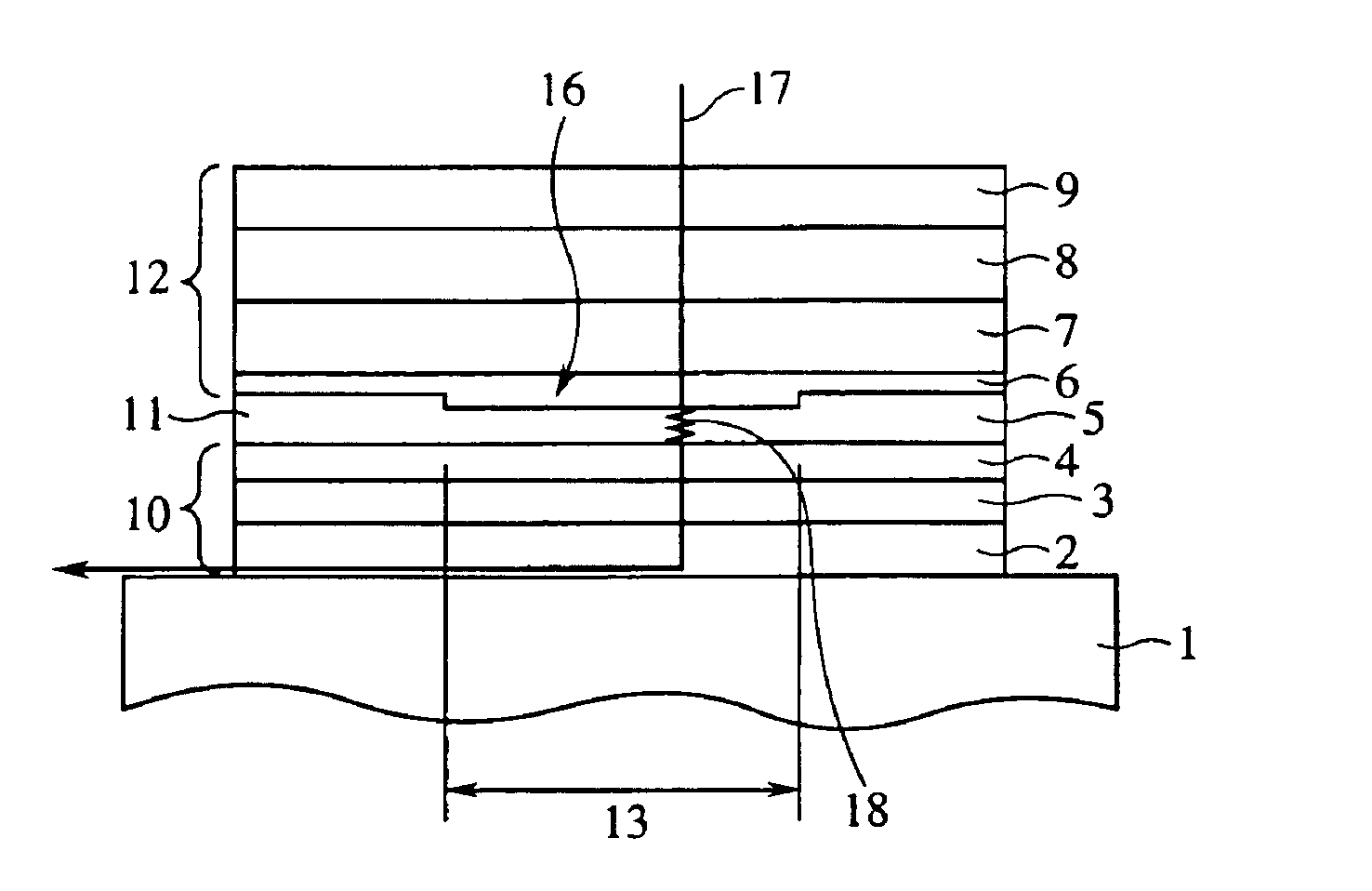
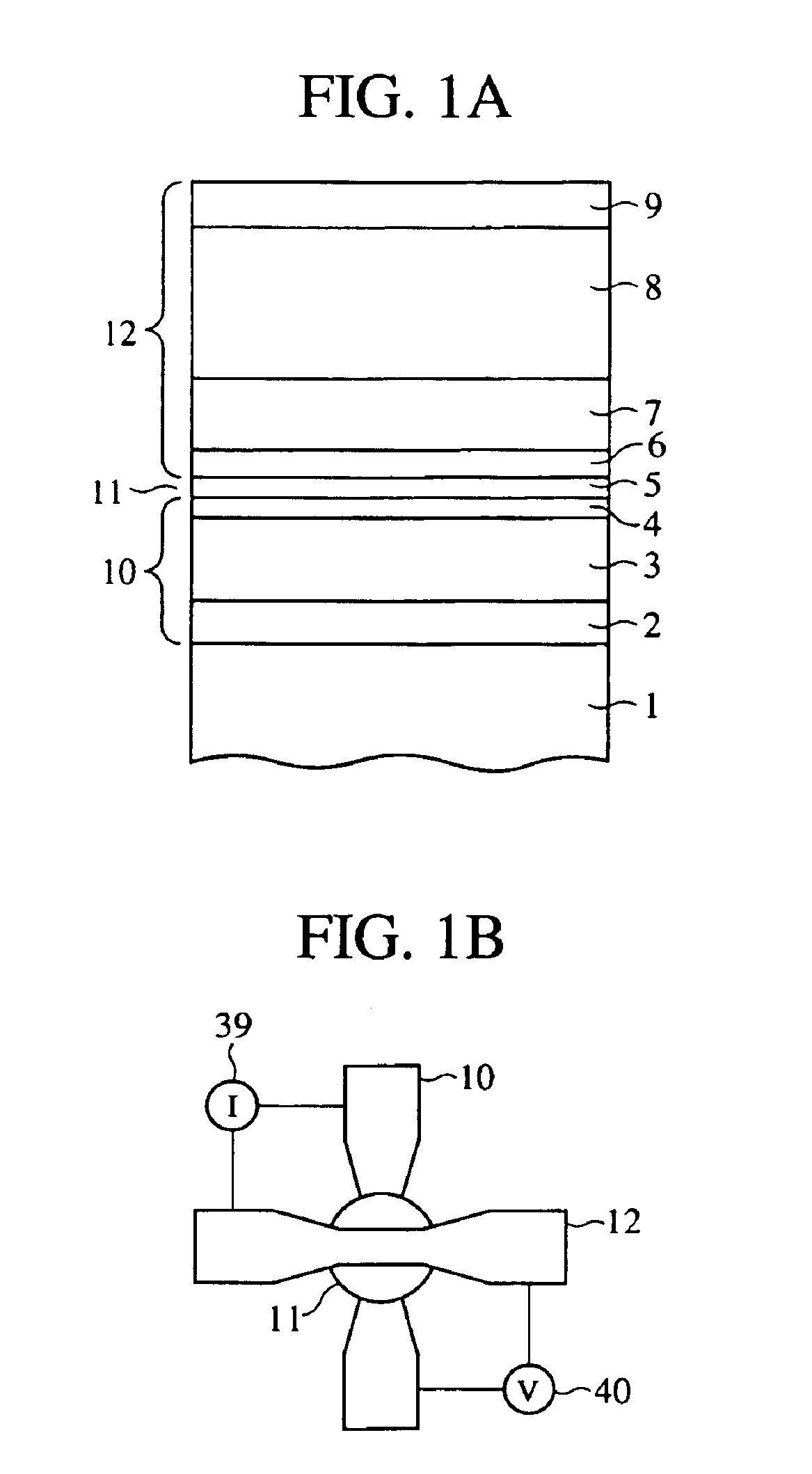
[0100]Here, a typical example of the magnetic sensor will be explained by means of the magnetic sensor having the spin valve structure. FIG. 7A is a view of a structure of the magnetic sensor according to the present embodiment, which has the spin valve structure and uses a tunnel junction. FIG. 7B shows, as a control, the structure of the magnetic sensor having the previously proposed spin valve structure.
[0101]As shown in FIG. 7A, the magnetic sensor according to the present embodiment has a tunnel junction of the spin valve structure disposed between a lower magnetic electrode 2 and an upper magnetic electrode 9. The spin valve st...
application example
[0150](Application Example to Magnetic Head)
[0151]The above-described magnetic sensor is typically applicable to magnetic heads. Recently as a magnetic head, a composite-type magnetic head using as the magnetic head an inductive head for recording, and a GMR head for reproduction which are integrated with each other has been developed and is practically used.
[0152]The GMR head typically has the spin valve structure (but has no tunnel junction). In place of the GMR head of the composite-type magnetic head, the magnetic sensor of the spin valve structure having the above-described tunnel junction is applicable as it is.
application examples
[0153](Other Application Examples)
[0154]An example of the application of the magnetic sensor according to the present invention to a magnetic encoder will be explained.
[0155]FIG. 13A is a view showing the magnetic sensor 50 according to the present invention, which is applied to a magnetic encoder. The magnetic sensor 50 includes an electric source terminal V, a ground terminal GND, an output A-terminal A-OUT and an output B-terminal B-OUT. As the magnetic sensor 50, a first ferromagnetic tunnel junction element TMR1 is jointed inserted between the electric source terminal V and the output A-terminal A-OUT, a second ferromagnetic tunnel junction element TMR2 is inserted between the electric source terminal V and the output B-terminal B-OUT, a third ferromagnetic tunnel junction element TMR3 is inserted between the ground terminal GND and the output A-terminal A-OUT, and a fourth ferromagnetic tunnel junction element TMR4 is inserted between the ground terminal GND and the output B-t...
PUM
 Abstract
Description
Claims
Application Information