Optical inspection system

an optical inspection system and optical technology, applied in the field of optical inspection systems, can solve problems such as object inspection systems, and achieve the effects of improving the functionality of object inspection systems, increasing the diversity of objects, and reducing limitations

Inactive Publication Date: 2007-04-03
ORBOTECH LTD
View PDF14 Cites 52 Cited by
  • Summary
  • Abstract
  • Description
  • Claims
  • Application Information

AI Technical Summary

Benefits of technology

[0024]All prior art object inspection systems suffer from certain limitations which make them useful for inspecting only certain types of objects, even if the objects being inspected are limited to the fields of printed circuit boards, integrated circuits, and similar electronic components. The present invention seeks to provide improved apparatus and methods of analyzing images, particularly color images, particularly for the purpose of improving the functionality of object inspection systems, increasing the diversity of objects that can be inspected by the system, and generally reducing the limitations thereof.
[0025]It is believed that improved color processing may be particularly effective in analyzing images of multi-colored objects, particularly in cases where a

Problems solved by technology

All prior art object inspection systems suffer from certain limitations which make them useful for inspecting only certain types of objects, e

Method used


Image

  • Optical inspection system
  • Optical inspection system
  • Optical inspection system

Examples


Embodiment Construction

Overview

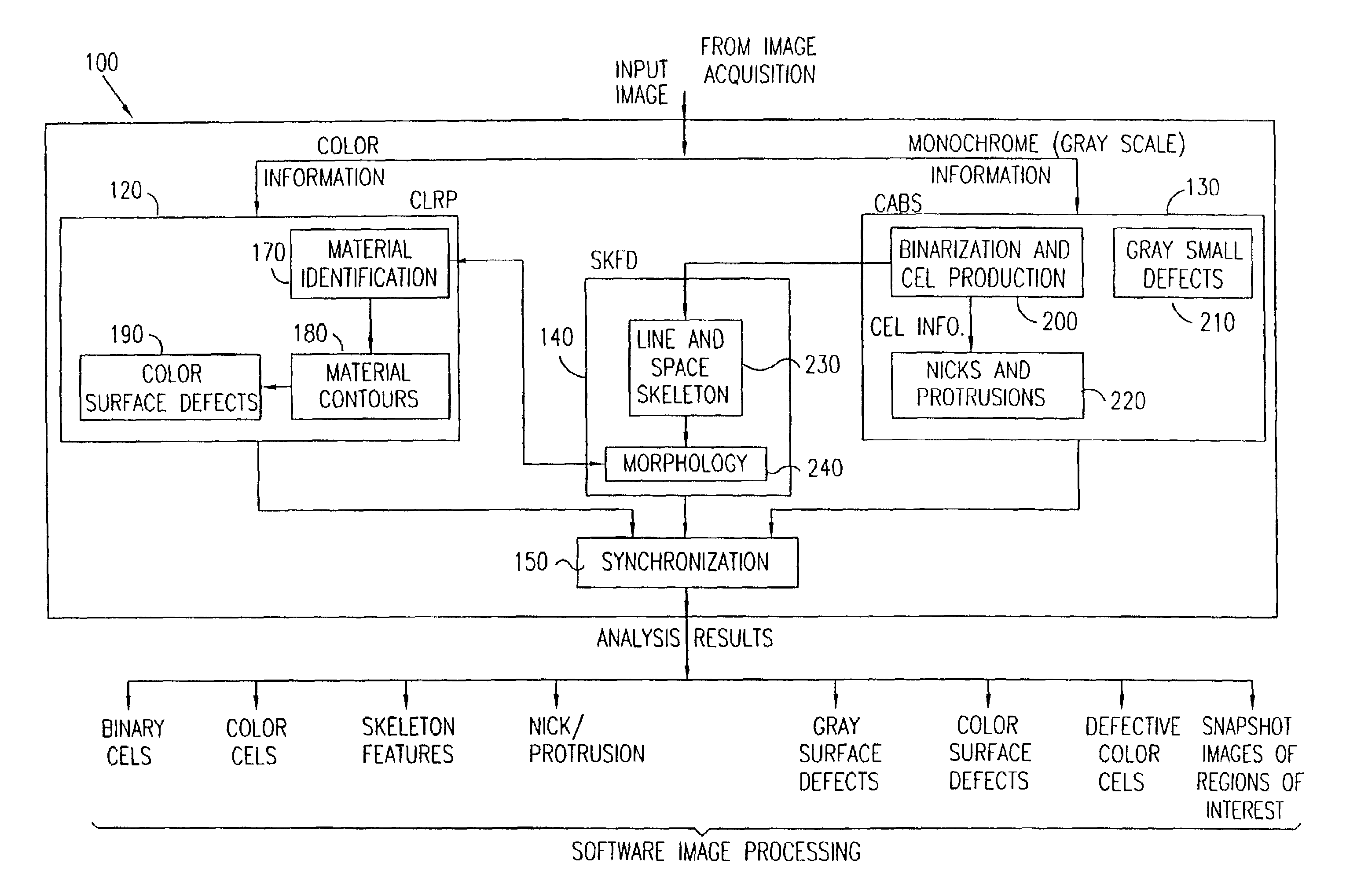
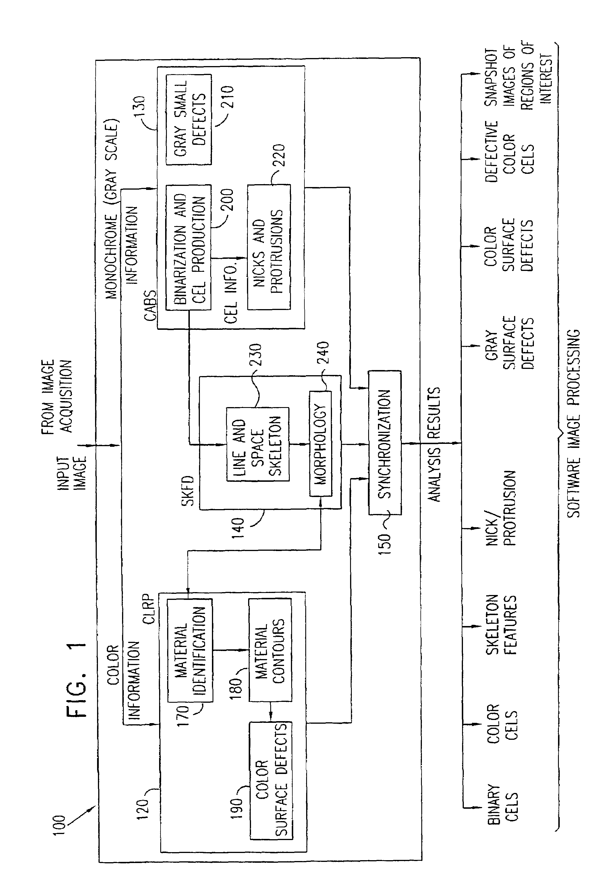
[0284]Reference is now made to FIG. 1 which is a simplified block diagram illustration of an image analysis system 100 constructed and operative in accordance with a preferred embodiment of the present invention. It is appreciated that, while the system of FIG. 1 is particularly useful in analyzing an image which represents a patterned object, for example a BGA or other electric circuit, the system of FIG. 1 may generally be useful in image analysis, whether or not an image being analyzed represents a patterned object or any other object. Although reference in the present specification is made to BGAs for the purposes of illustrating the present invention, the term BGA as used in the present specification shall be deemed to refer to and additionally include printed circuit board substrates, laminated printed circuit boards, lead frames, flat panel displays, hybrid chip packaging substrates, tape automated bonding substrates, and any suitable patterned object including variou...


PUM


Abstract

This invention discloses a method for determining a location of a border in a color image, the image comprising at least two color populations, between a first color region associated with a first one of the two color populations and a second color region associated with a second one of the two color populations, both the first color region and the second color region being comprised in the color image, the method includes identifying an approximate border location between the first color region and the second color region, determining a plurality of candidate border locations between the first color region and the second color region, each of the plurality of candidate border locations being determined by applying a corresponding border location method chosen from among a plurality of border location methods, choosing one method from among the plurality of border location methods as a preferred method, and determining a location of a border between the first color region and the second color region by designating one of the plurality of candidate border locations associated with the preferred method as the border. An automated optical inspection device suitable for inspection of patterned articles is also disclosed.

Description

FIELD OF THE INVENTION[0001]The present invention relates to apparatus and methods for analyzing images, especially but not exclusively color images, and more specifically to apparatus and methods of image analysis which are useful in inspection of a patterned object.BACKGROUND OF THE INVENTION[0002]Apparatus and methods for analyzing images, and in particular for image analysis which is useful in inspection of a patterned object, are well known in the art.[0003]The following references describe image processing methods which may be useful in understanding the present invention:[0004]C. Gonzalez and P. Wintz, Digital Image Processing, Addison Wesley, Reading, Mass., 1987; and[0005]John C. Russ, The Image Processing Handbook, CRC Press, 1994.[0006]The following references describe edge detection methods which may be useful in understanding the present invention:[0007]D. Marr and E. Hildreth, Theory of Edge Detection, Proceedings of the Royal Society of London; and[0008]M. Chapron, “A...

Claims


Application Information

Patent Timeline
IPC IPC(8): G06K9/00G01B11/00G01N21/88G01N21/956G06T1/00G06T5/00G06T7/00G06T7/60
CPCG06K9/0014G06T7/0004G06T7/0083G06T7/0091G06T2207/10016G06T2207/30141G06T7/12G06T7/155G06V20/695
Inventor GOLD, URIPARENTE, ELIGILAT-BERNSHTEIN, TALLYBARANOVSKY, EDWARDMARGALIT, TAMIR
Owner ORBOTECH LTD
Why Eureka
Try Eureka