
High count telecommunication optical cable with controlled fiber length method and apparatus for manufacturing the same

a technology of optical cable and control cable, which is applied in the field of telecommunication optical cable, can solve the problems of increasing the size of the optical cable category, reducing the service life of the cable, and providing no substantial resistance to the axial compression force applied to the cable, etc., and achieves the effects of reducing the size, reducing the cost of operation, and controlling the optical attenuation

Inactive Publication Date: 2007-04-03
PRYSMIAN CAVI E SISTEMI ENERGIA
View PDF14 Cites 42 Cited by
  • Summary
  • Abstract
  • Description
  • Claims
  • Application Information

AI Technical Summary

Benefits of technology

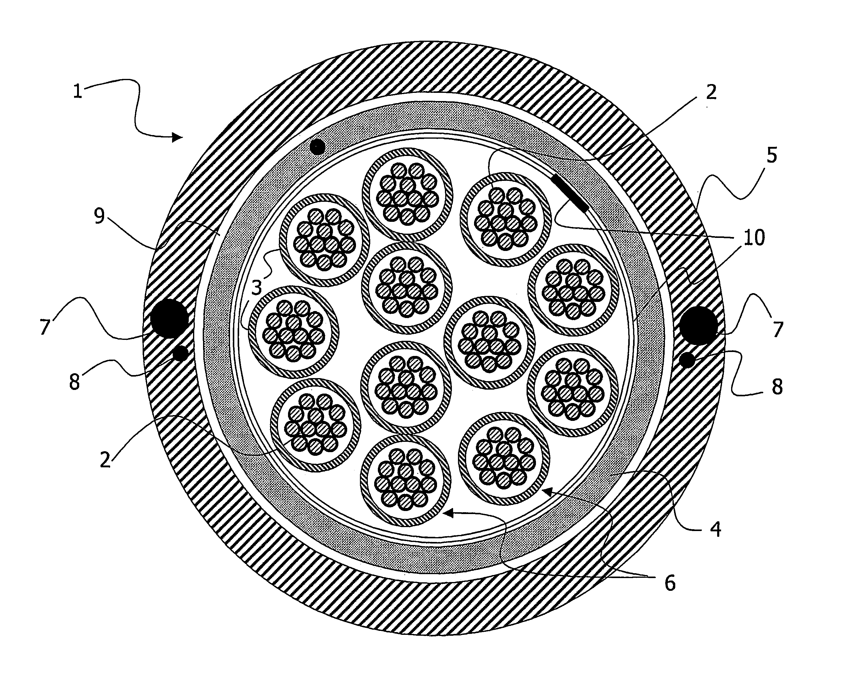
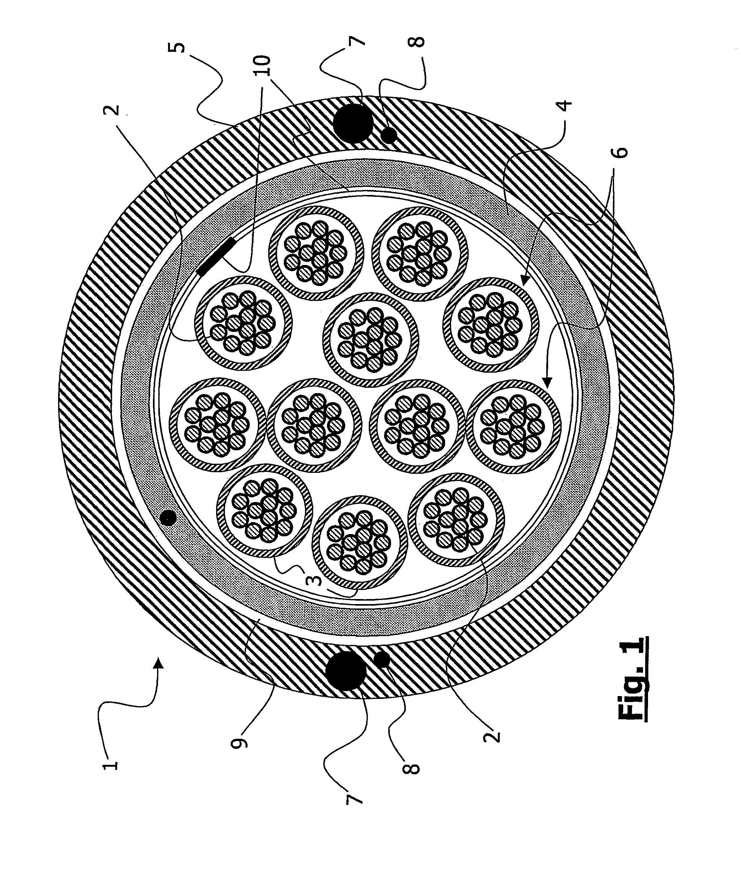
[0033]An object of the present invention is providing a telecommunication loose microbundle optical cable having an equalized / controlled fiber length variation and, therefore, having a controlled optical attenuation. High thermal stability and reduced size are further desired characteristics.
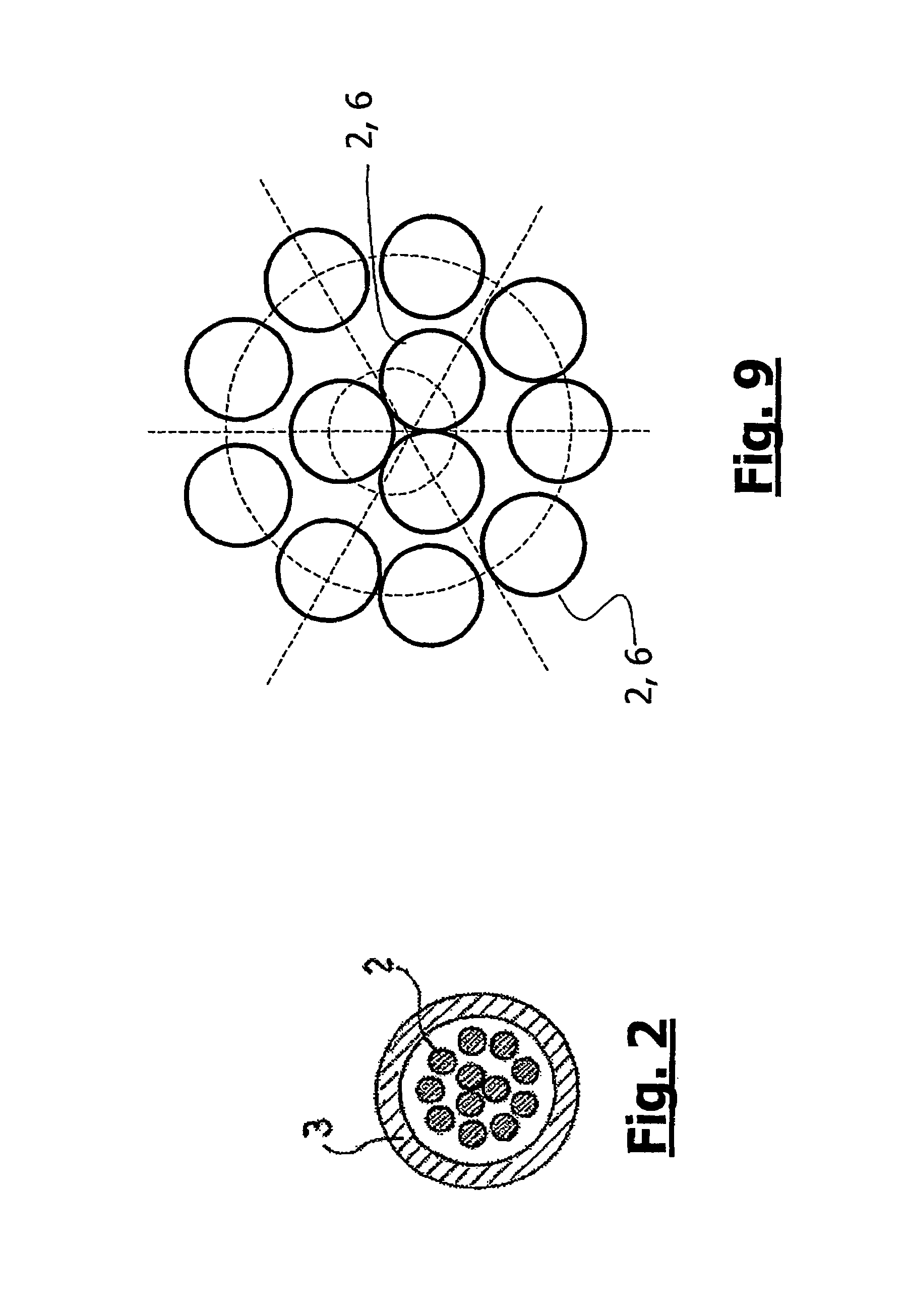
[0036]The Applicant has found that, by arranging in open helix the fibers inside the microbundles of a loose microbundles optical cable, the resulting cable has an equalized / controlled fiber length variation, a controlled optical attenuation, a high thermal stability and a reduced size. The loose cable according to the present invention shows the same minimized length difference in any spans thereof.
[0037]In particular, the Applicant has verified that by arranging the fibers according to an open helix inside the microbundle it is possible to obtain a length difference lower than 0.035% of these fibers.
[0050]According to a different aspect thereof, the present invention relates to an apparatus for manufacturing a telecommunication optical cable comprising: an optical fiber pay-off stand suitable for unwinding a plurality of optical fibers; an extrusion device for extruding, around said plurality of optical fibers, a microsheath loosely containing said plurality of optical fibers to form a microbundle; wherein the apparatus comprises a fiber oscillating device between the fiber pay-off stand and the extrusion device, for SZ oscillating the fibers before entrance into the extrusion device, and a fiber guide member placed before the fiber oscillating device, for properly arranging the optical fibers in a predetermined configuration.

Problems solved by technology

The yarns of aramid material or glass form reinforcement against traction forces but they provide no substantial resistance to axial compression forces applied to the cable.
The generated fiber optic bendings could be divided into microbendings and macrobendings but, in any case, they originate unwanted optical attenuation increases.
In addition to the above problems of the known Multi Loose Tube optical cables, a further disadvantage of such an optical cable category lies in the size.
A high diameter optical cable is undesirable both for installation and production reasons (high costs, disadvantageous installation, bulky winding bobbin).
A further disadvantage of the known Multi Loose Tube optical cables is that the tube are made of a material which is rather tough such as, for instance, high density polythene or polybutylene therephtalate.
This results in the need to use a special tool for removing or stripping the tubes.
Notwithstanding the above advantages, it has been found that a known microbundle optical cable still has considerable and highly undesirable optical attenuation problems.
A similar problem occurs when the inner tube is manufactured starting from the microbundles, if the microbundles are provided straight (i.e. parallel to each other).
These length differences result in microbending and / or macrobending problems that will negatively affect the cable attenuation performances.

Method used


Image

  • High count telecommunication optical cable with controlled fiber length method and apparatus for manufacturing the same
  • High count telecommunication optical cable with controlled fiber length method and apparatus for manufacturing the same
  • High count telecommunication optical cable with controlled fiber length method and apparatus for manufacturing the same

Examples


examples

[0140]Before testing the technique of the present invention, the Applicant has estimated the fiber length difference that would result by winding on a capstan a microbundle having straight fibers (i.e. not SZ stranded). By simple calculations it is possible to demonstrate that a microbundle with internal diameter of 1.1 mm and straight fibers, wound onto the pulley of a capstan of 320 mm of diameter, shows a length difference of about 0.3% between the fiber that is closer to the pulley surface and the fiber that is more distant to it.

[0141]The Applicant has then performed some experiments in the following process conditions, using the manufacturing line 100 (with three cooling through 106) for manufacturing a microbundle 6:[0142]Line speed: 140 m / min;[0143]Fiber back tension: 50±10 g;[0144]Lay plate: 3 central holes and 9 external holes on a circumference of 7.5 mm of diameter;[0145]Extrusion head tooling: 1.9 mm (tip)–2.25 mm (die);[0146]Water temperature in the cooling through: 40...


PUM

PropertyMeasurementUnit
Lengthaaaaaaaaaa
Fractionaaaaaaaaaa
Thicknessaaaaaaaaaa

Abstract

A telecommunication optical cable has a number of optical fibers; at least a microsheath loosely containing the optical fibers, the at least one microsheath loosely containing the optical fibers therein forming at least one corresponding microbundle, wherein the optical fibers are stranded according to an open helix trajectory.

Description

CROSS REFERENCE TO RELATED APPLICATIONS[0001]This application is a national phase application based on PCT / EP2002 / 013682, filed Dec. 3, 2002, the content of which is incorporated herein by reference.BACKGROUND OF THE INVENTION[0002]1. Field of the Invention[0003]The present invention relates to telecommunication optical cables and in particular it relates to an optical telecommunication cable having a controlled fiber length. The present invention further relates to a method and an apparatus for manufacturing such a controlled fiber length optical cable.[0004]2. Description of the Related Art[0005]Several different telecommunication optical cables are known in the art. A widely used type of optical cable is the so-called Multi Loose Tube (MLT) cable, an example of which is described in U.S. Pat. No. 5,999,677. A typical MLT cable comprises: a central strength member; a number of tubes containing loosely placed optical fibers; a mechanical reinforcing layer, for example a thread made...

Claims


Application Information

Patent Timeline
IPC IPC(8): G02B6/44B23P25/00B29D11/00
CPCG02B6/4484G02B6/449G02B6/441Y10T29/49Y10T29/49885
Inventor BAU', FABIOGINOCCHIO, ALESSANDRO
Owner PRYSMIAN CAVI E SISTEMI ENERGIA
Learn More