Internal combustion engine

a technology of internal combustion engine and combustion chamber, which is applied in the direction of combustion engine, fuel injection apparatus, charge feed system, etc., can solve the problems of limiting the power output of the engine, inability to fully burn enough fuel per power stroke in the comparatively small cylinder of the more power dense engine, and failure to meet the requirements of certain limits

Active Publication Date: 2007-04-10
CATERPILLAR INC
View PDF8 Cites 4 Cited by
  • Summary
  • Abstract
  • Description
  • Claims
  • Application Information

AI Technical Summary

Problems solved by technology

However, attempts to scale down many internal combustion engines below certain limits have met with little success, particularly with regard to direct injection compression ignition engines.
Many smaller, theoretically more power dense engines may be incapable of fully burning sufficient fuel per each power stroke in their comparatively small cylinders to meet higher power demands.
For example, if a conventional engine is running at a lower temperature and boost, where relatively small fuel quantities are injected for each cycle, and more power is demanded of the engine, an inability to burn the higher demanded fuel quantities may limit the engine's power output.
This problem is particularly acute in smaller bore engines.
Wall wetting can thus limit small bore engines to lower power and worse emissions than what intuitively could be their inherent capabilities, as wall wetting tends to cause poor combustion and high hydrocarbon and particulate emissions.
Inadequate mixing of the fuel and air, however, can cause excessive smoke before combustion, limiting the engine's power long before its theoretical power limit is reached.
One reason for these limitations is that at higher RPMs, there is only a relatively small amount of time within which to inject and ignite fuel in each cylinder.
However, neither type of engine is typically capable of providing an attractive power density commensurate with their size and weight.
Although the TKDI 600 is claimed to have certain applications, such as in a small unmanned aircraft, the available BMEP is relatively low, about 169 PSI and the engine is therefore somewhat limited in its total available power output and hence, power density.

Method used


Image

  • Internal combustion engine
  • Internal combustion engine
  • Internal combustion engine

Examples


Embodiment Construction

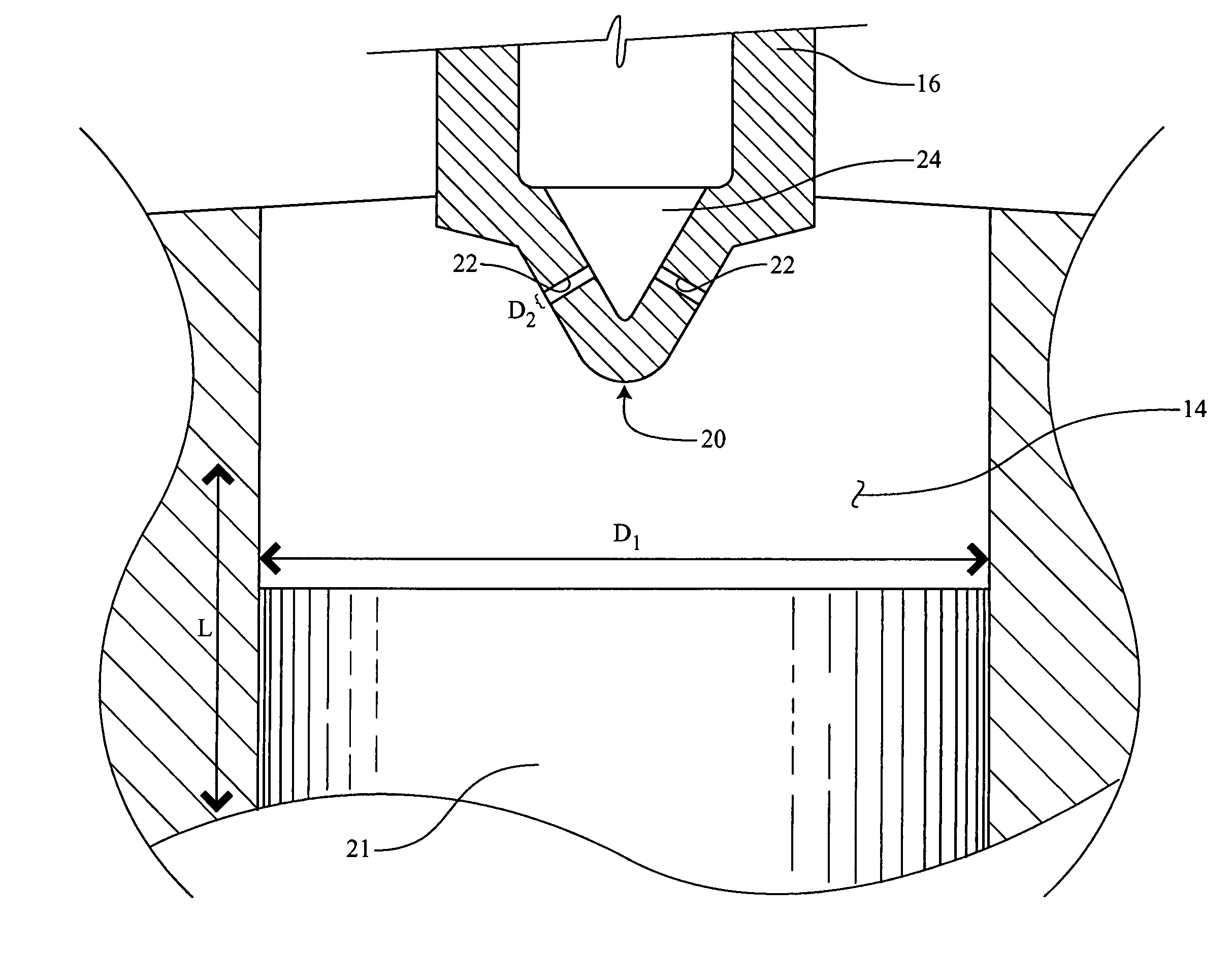
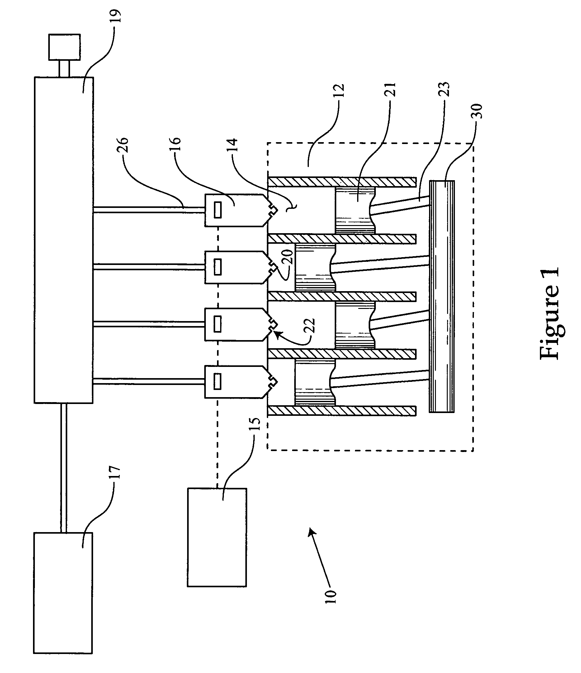
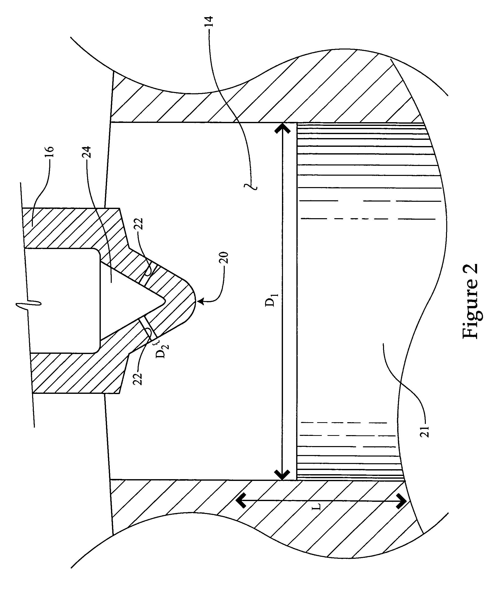
[0016]Referring to FIG. 1, there is shown a schematic illustration of an engine 10 according to one embodiment of the present disclosure. Engine 10 includes an engine housing 12 having a plurality of cylinders 14 therein. A fuel injector 16 is disposed at least partially within each of cylinders 14 and operable to direct inject a liquid fuel therein. Each of fuel injectors 16 may include a fuel injector tip 20 extending into the associated cylinder, and each tip 20 has a plurality of outlet orifices 22. Engine 10 further includes a plurality of pistons 21, each disposed at least partially within one of cylinders 14 and movable therein, and each piston is coupled with a crankshaft 30 via a piston rod 23. Engine 10 may further include a pressurized fuel source 17, which may include a high pressure pump or cam-actuated fuel pressurizer, for example. Pressurized fuel source 17 may be fluidly connected with each of fuel injectors 16 via a high pressure feed line or common rail 19 and a p...


PUM


Abstract

The present disclosure provides an internal combustion engine having an engine housing with at least one cylinder that has diameter less than about 3 inches. A fuel injector is provided and disposed at least partially within the at least one cylinder, and includes a plurality of outlet orifices having a diameter between about 50 microns and about 110 microns. The disclosure further provides a method of operating an internal combustion engine. The method includes the steps of rotating an engine crank shaft of the engine at a speed greater than about 5000 revolutions per minute, injecting a quantity of fuel into each of the cylinders, and burning at least every fourth piston stroke a sufficient quantity of the injected fuel to yield a brake mean effective pressure of at least about 200 lbs. per square inch.

Description

TECHNICAL FIELD[0001]The present disclosure relates generally to internal combustion engines, and relates more particularly to small bore direct injection internal combustion engines that utilize fuel injectors with tiny outlet orifices.BACKGROUND[0002]Internal combustion engines have long been used as power sources in a broad range of applications. Internal combustion engines may range in size from relatively small, hand held power tools to very large diesel engines used in marine vessels and electrical power stations. In general terms, larger engines are more powerful, whereas smaller engines are less powerful. Engine power can be calculated with the following equation, where “BMEP” is brake mean effective pressure, the average cylinder pressure during the power stroke of a conventional four-stroke piston engine:Power=(BMEP)×(Engine Displacement)×(RPM)×( 1 / 792,000).(English Units)[0003]While larger engines may be more powerful, their power-to-weight or size ratio or “power-density...

Claims


Application Information

Patent Timeline
Patent Type & Authority Patents(United States)
IPC IPC(8): F02B17/00B05B1/00
CPCF02B3/06F02M61/1846Y02T10/12
Inventor VACHON, JOHN T.
Owner CATERPILLAR INC
Why Eureka
Try Eureka