Control for a hydrostatic power train

a technology of hydrostatic power train and control device, which is applied in the direction of gearing control, external condition input parameters, application, etc., can solve the problems of reducing the transmitted torque to one of the axles before a slippage on one of the axles, and affecting the operation of the control device. , to achieve the effect of constant absorption volume and high speed of motion

Inactive Publication Date: 2007-04-10
HYDROMATIK GMBH
View PDF11 Cites 10 Cited by
  • Summary
  • Abstract
  • Description
  • Claims
  • Application Information

AI Technical Summary

Benefits of technology

[0013]It is particularly advantageous to provide, on the control valve or control valve unit, an additional switching position, in which both the hydraulic motor unit of the front axle and the hydraulic motor unit of the rear axle are adjusted in the direction of smaller absorption volume, to make a higher speed of motion possible, e.g. for transport.
[0014]A further advantage is, simultaneously with the adjustment of a hydraulic motor unit in the direction of smaller torque, to adjust the absorption volume of the other hydraulic motor unit oppositely, in the direction of greater absorption volume, so that the sum of the absorption volumes remains constant. For this purpose, a hydraulic motor unit consisting of several hydraulic motors, each of which has a constant absorption volume, can be used specially advantageously. To change the absorption volume of such a hydraulic motor unit, one of the hydraulic motors can then be switched on or off.

Problems solved by technology

The system which is proposed in DE 101 01 748 A1 has the disadvantage that the cost of construction is relatively great.
The system which is known from DE 196 38 421 A1 has the disadvantage that the traction controller intervenes only when a slip has already occurred.
On the other hand, reduction of the transmitted torque to one of the axles before a slip occurs on one of the axles is not provided.

Method used


Image

  • Control for a hydrostatic power train
  • Control for a hydrostatic power train
  • Control for a hydrostatic power train

Examples


first embodiment

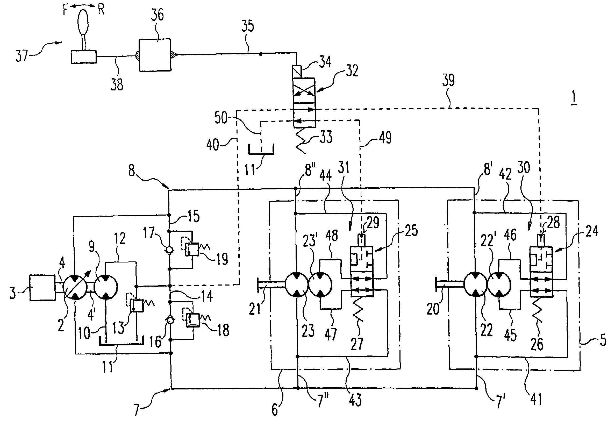
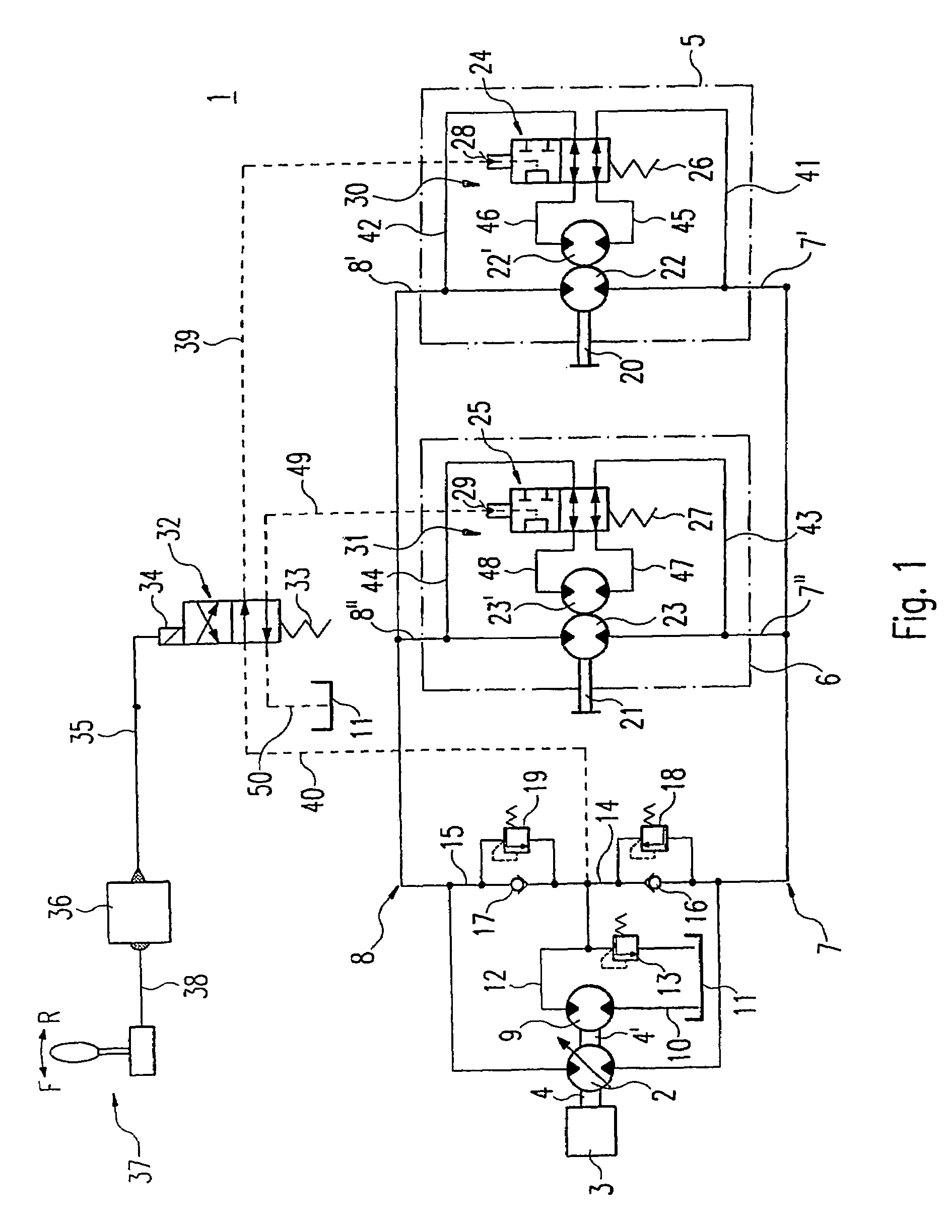
[0024]a controller according to the invention for a hydrostatic traversing mechanism is shown in FIG. 1. A hydrostatic traversing mechanism 1 includes a pump 2, which is driven by a prime mover 3. The pump 2 is connected via a drive shaft 4 to the prime mover 3. The hydrostatic traversing mechanism also includes a first hydraulic motor unit 5 and a second hydraulic motor unit 6. The first hydraulic motor unit 5 and the second hydraulic motor unit 6 are connected in parallel via a first main duct 7 and a second main duct 8 to the pump 2. Depending on the delivery direction of the pump 2, the hydraulic fluid is fed from the first main duct 7 via a first connecting duct 7′ to the first hydraulic motor unit 5, and via a second connecting duct 7″ to the second hydraulic motor unit 6, or, in the case of delivery in the opposite direction, from the second main duct 8 via a third connecting duct 8′ to the first hydraulic motor unit 5, and via a fourth connecting duct 8″ to the second hydrau...

second embodiment

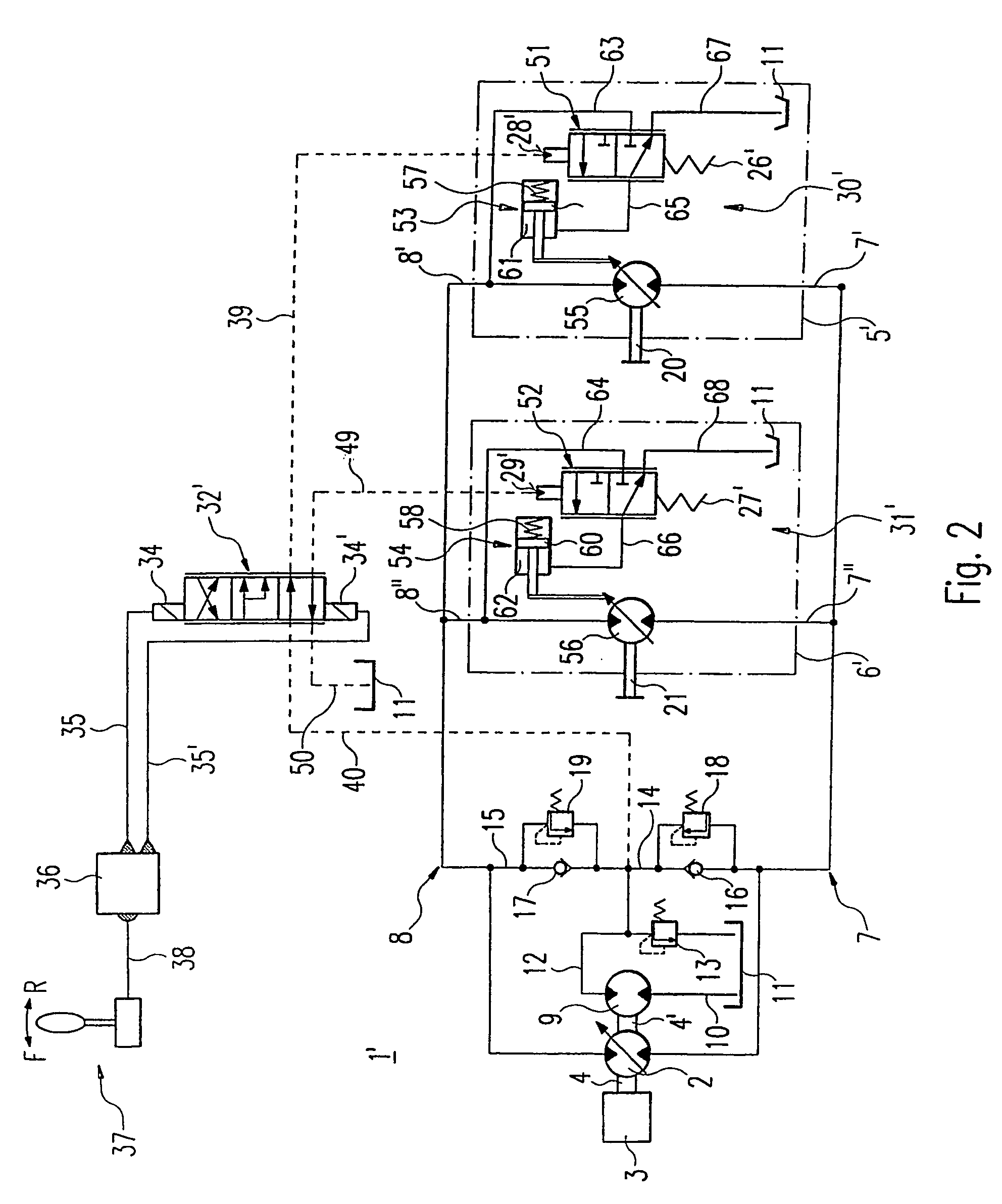
[0041]In FIG. 2, a controller according to the invention is shown. Identical components are given identical reference symbols. To avoid repetitions, reference is made to the description of FIG. 1.

[0042]In contrast to the first embodiment of FIG. 1, in the hydrostatic traversing mechanism according to FIG. 2 a first hydraulic motor unit 5′ and a second hydraulic motor unit 6′, which have a first hydraulic motor 55 and a second hydraulic motor 56 respectively, are provided. The absorption volume of the first and second hydraulic motor 55 and 56 is adjustable. For instance, machines in swash plate construction, in which the absorption volume is adjusted by adjusting the pivoting angle of the swash plate, can be used.

[0043]To adjust the absorption volume of the first hydraulic motor 55 or second hydraulic motor 56, a control valve 32′, which can take a first and a second switch position which are identical to the first and second switch position of the control valve 32 from FIG. 1, is p...


PUM


Abstract

A hydrostatic power train includes a hydraulic pump, which is connected, via a first main pipe and a second main pipe, to a first hydromotor unit driving a front axle and to a second hydromotor unit driving a rear axle. The first and second hydromotor units can be adjusted in terms of their displacement via a first and second variation device. A direction of travel is defined as forward movement (F) or reverse movement (R) by a position of an operating lever. The first and the second variation devices are controlled by a control valve which takes up a first control position upon a forward movement (F) determined by the position of the operating ever and which takes up a second control position upon reverse movement (R) determined by the position of the operating lever and which takes up a second control position upon reverse movement (R) determined by the operating lever. In the first control position, the first variation device is controlled such that the first motor unit is adjusted for a smaller displacement and, in the second control position; the second variation device is controlled such that the second motor unit is adjusted for a smaller displacement.

Description

BACKGROUND OF THE INVENTION[0001]1. Field of the Invention[0002]The invention concerns a controller for a hydrostatic traversing mechanism.[0003]Hydrostatic traversing mechanisms, in which two hydraulic motors are connected to a hydraulic pump and the hydraulic pump is driven by a driving motor, are known as traversing mechanisms of working machines such as road rollers. In such a system, in which one hydraulic motor each is assigned to the front and rear axles, to adapt the torque distribution of the individual motors to the conditions of use, e.g. uphill and downhill, various systems for traction control are known.[0004]2. Discussion of the Prior Art[0005]In DE 101 01 748 A1, for instance, a system in which signals from pressure sensors, which are arranged in the pressure-side and induction-side main duct, are fed to an electronic control unit, is proposed. On the basis of changes of the pressure signals and changes of the position of a driving lever, the electronic control unit d...

Claims


Application Information

Patent Timeline
Patent Type & Authority Patents(United States)
IPC IPC(8): B60K28/16B60K17/356F16H59/66F16H61/42F16H61/423F16H61/448F16H61/456
CPCB60K17/356B60K28/165F16H61/42F16H61/423F16H61/448F16H61/456B60W2300/50B60W2550/142B60Y2200/413F16H59/66F16H2059/6861F16H2059/663B60W2552/15
Inventor SHRIVE, CHRISPERRY, GRAHAMESSIG, HEINZ-GERHARD
Owner HYDROMATIK GMBH
Why Eureka
Try Eureka