
Servo write method for magnetic tape

a write method and magnetic tape technology, applied in the direction of maintaining head carrier alignment, manufacturing head surface, instruments, etc., can solve the problem of leading edge wear of the head, and achieve the effect of reducing the wear of the magnetic recording region, enhancing the servo pattern, and prolonging the life of the head

Inactive Publication Date: 2007-04-17
HEWLETT-PACKARD ENTERPRISE DEV LP
View PDF9 Cites 25 Cited by
  • Summary
  • Abstract
  • Description
  • Claims
  • Application Information

AI Technical Summary

Benefits of technology

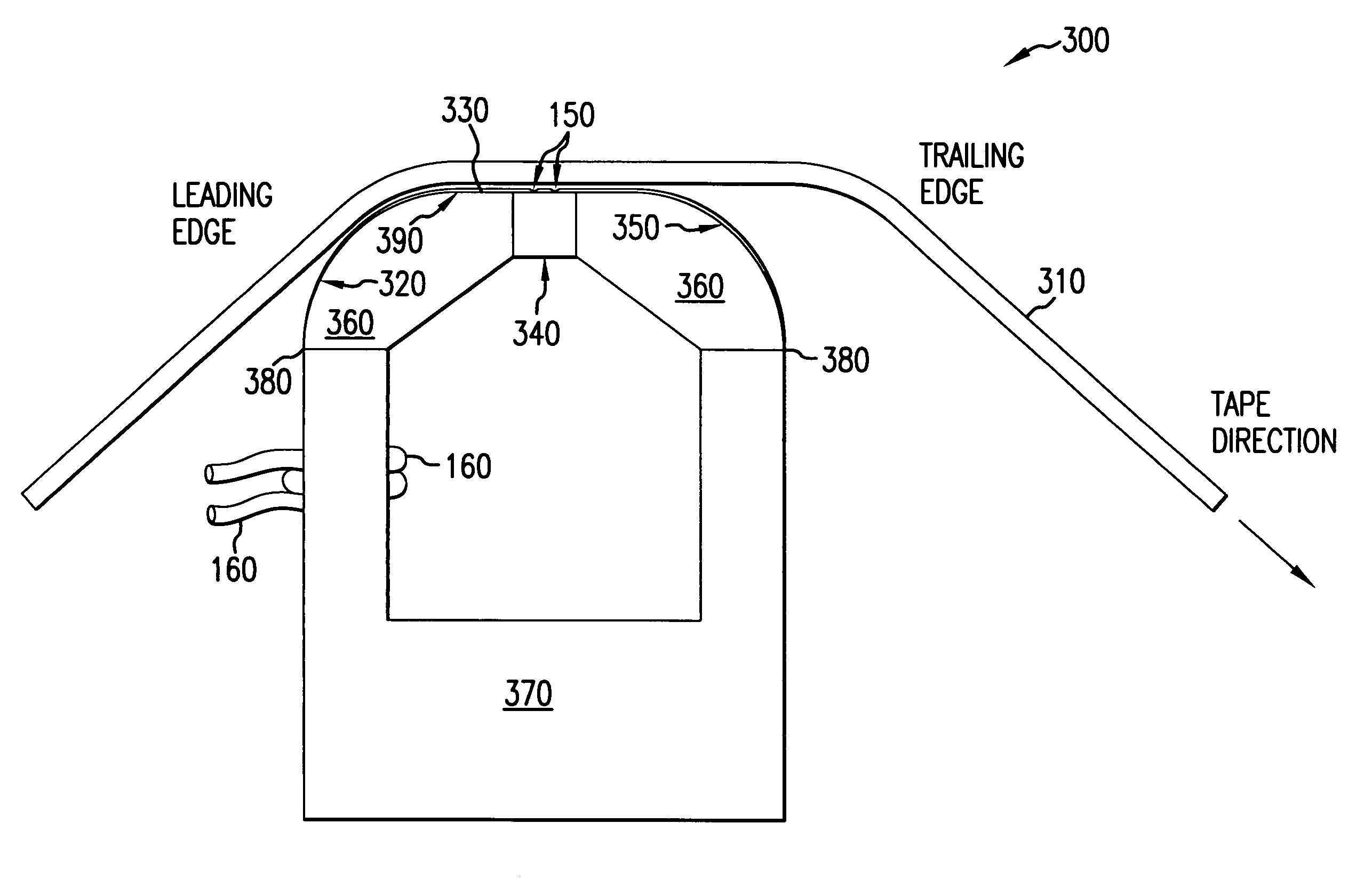
[0011]A batch fabrication technique is described that increases the manufacturing efficiency of servo write heads and also improves servo pattern definition for fine features, while reducing tape and head wear. Multiple heads are fabricated as a batch from one or more ferrite wafers. A nominally flat, large wafer surface and a contour suitable for uniform photoresist application and planar photolithography permit fine servo pattern definition. A rounded leading edge on the head creates an air bearing to reduce wear of the tape and of the head. Moreover, any head wear occurs at the leading edge rather than in the region of the head where the servo pattern is formed.
[0013]The head can advantageously permit single pass recording of servo data over the width and length of the tape. A head as described will experience reduced wear of the magnetic recording region of the head. In a preferred embodiment, the geometry of the head will cause low contact pressure on tape at the edges of head so that any wear occurring at edges of the head will be reduced and head life will be extended.
[0014]According to another aspect of the invention, the head is formed from an upper ferrite wafer having a non-magnetic spacer. Non-magnetic material is photolithographically defined to produce gaps above the spacer. The non-magnetic material may be photoresist, semiconductor materials, glass, metal or the like. The material may even be removed later to leave air gaps. The non-magnetic material forms a region where the field loops out to intersect the passing tape, thereby transferring a magnetic pattern to tape. The defined gap pattern may differ from the pattern written to tape. By appropriate choice of gap pattern, the servo pattern may be enhanced. An additional non-magnetic space can be formed in the back of the upper ferrite wafer proximate to the spacer to enhance the magnetic circuit. Additionally, a lower ferrite wafer may be mated to the upper ferrite wafer to complete a magnetic circuit around the gaps. An inductive winding may pass through a channel in the ferrite or spacer. Multiple heads may be formed through batch processing of the upper and lower ferrite wafers.
[0015]Furthermore, the design of the head is such that the head can be readily made through batch fabrication. Moreover, the head will permit fabrication with increased process control as well as increased general dimensional control. The potential for decreased linewidth will permit a more efficient write and more precise position signal, improving servo control. The write efficiency is further enhanced through completion of a magnetic circuit around the gaps.

Problems solved by technology

Moreover, any head wear occurs at the leading edge rather than in the region of the head where the servo pattern is formed.

Method used


Image

  • Servo write method for magnetic tape
  • Servo write method for magnetic tape
  • Servo write method for magnetic tape

Examples


Embodiment Construction

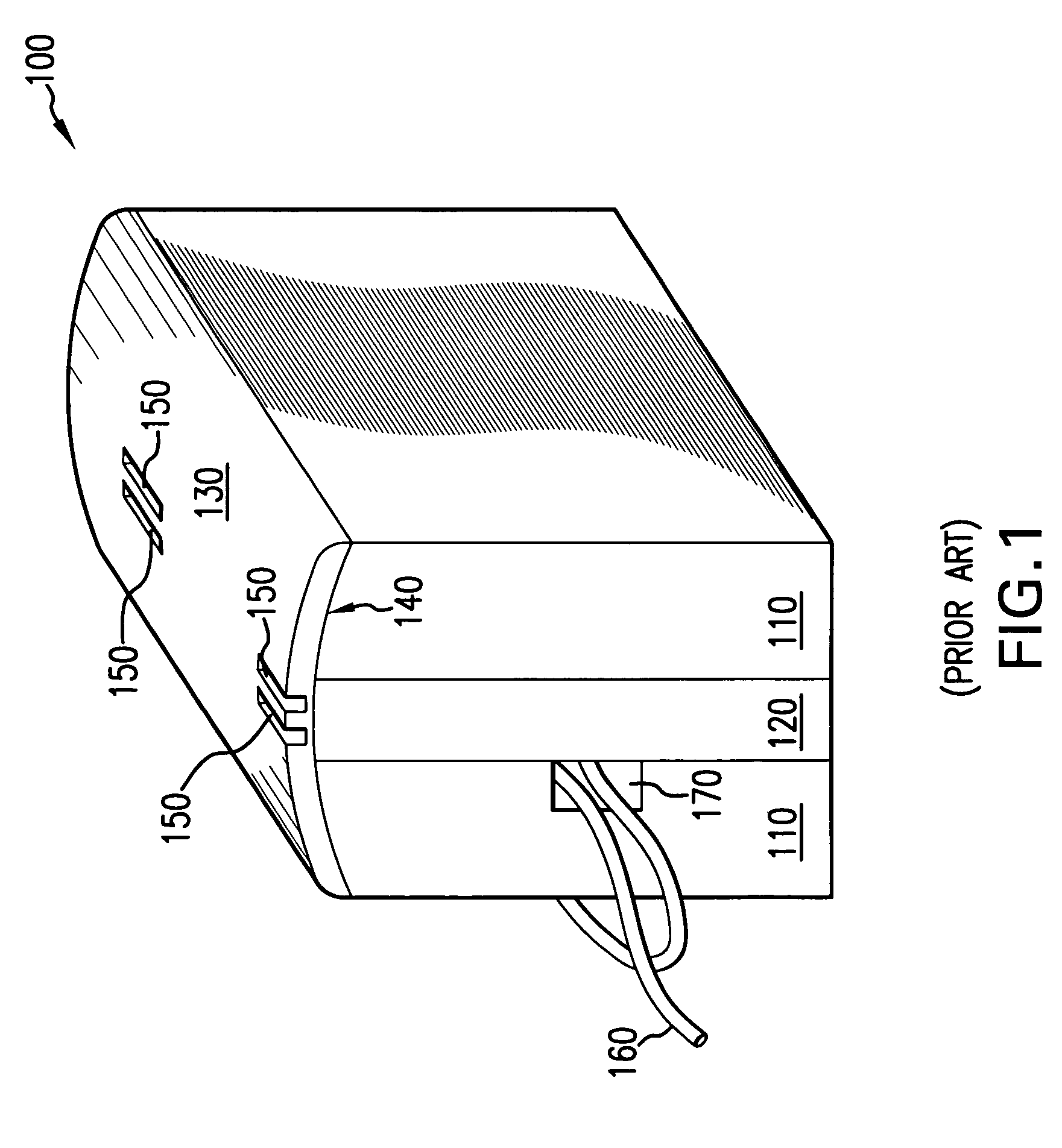
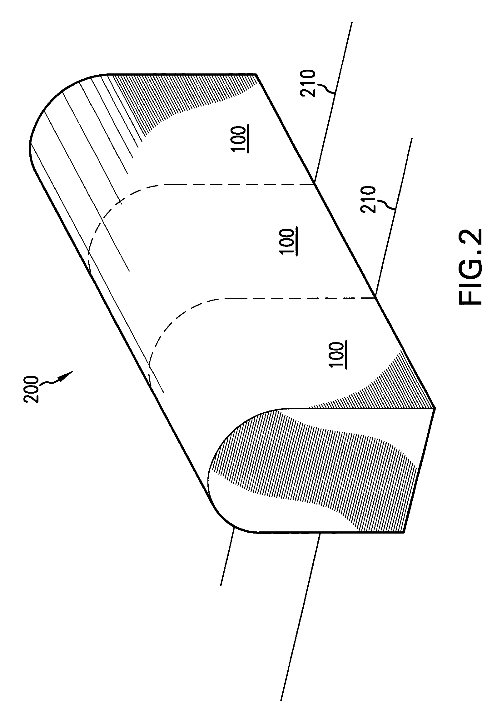
[0031]Embodiments of the invention are discussed below with reference to FIGS. 1–14. Those skilled in the art will readily appreciate that the detailed description given herein with respect to these figures is for explanatory purposes, however, because the invention extends beyond these limited embodiments.

[0032]The present invention is intended to be used for writing position servo information on magnetic tape in a manner similar to the head described by Albrecht et al., in European Patent Application EP 0 690 442 A2, supra.

[0033]FIG. 3 is a drawing illustrating a cross section of a servo write head 300 with recording tape 310 passing over the head 300 according to one embodiment of the present invention. The tape 310 first contacts the head 300 on the curved surface 320 located at the leading edge of the head 300. Tape 310 continues over the flat surface 330 supported by an air bearing which has formed between the tape 310 and the head surface 330.

[0034]To replicate the servo code...


PUM

PropertyMeasurementUnit
angleaaaaaaaaaa
radiusaaaaaaaaaa
wearaaaaaaaaaa

Abstract

A batch fabrication technique is described that increases the manufacturing efficiency of servo write heads and also improves servo pattern definition for fine features, while reducing tape and head wear. Multiple heads are fabricated as a batch from one or more ferrite wafers. A nominally flat, large wafer surface and a contour suitable for uniform photoresist application and planar photolithography permit fine servo pattern definition. A rounded leading edge on the head creates an air bearing to reduce wear of the tape and of the head. Moreover, any head wear occurs at the leading edge rather than in the region of the head where the servo pattern is formed. The servo write head may have a substantially planar head surface. A leading edge is disposed adjacent to the head surface such that the tape contacts the leading edge before passing over the head surface. The leading edge is rounded to form an air bearing between the head surface and the tape. A rounded trailing edge may be disposed adjacent to the head surface such that the tape passes over the trailing edge after passing over the head surface. The head may be formed from an upper ferrite wafer having a non-magnetic spacer. Non-magnetic material is photolithographically defined to produce gaps above the spacer. The non-magnetic material may be photoresist, semiconductor materials, glass, metal or the like. The material may even be removed later to leave air gaps. The non-magnetic material forms a region where the field loops out to intersect the passing tape, thereby transferring a magnetic pattern to tape. Additionally, a lower ferrite wafer may be mated to the upper ferrite wafer to complete a magnetic circuit around the gaps. The upper or lower ferrite wafer may have a channel through which an inductive winding passes. Multiple heads may be formed through batch processing of the upper and lower ferrite wafers.

Description

RELATED APPLICATIONS[0001]This patent application is a divisional of application Ser. No. 10 / 256,572, filed on Sep. 27, 2002, now U.S. Pat. No. 6,999,274, which is a continuation of application Ser. No. 09 / 791,903, filed on Feb. 22, 2001, now U.S. Pat. No. 6,647,613, which is a divisional of application Ser. No. 09 / 449,010, filed on Nov. 24, 1999, now U.S. Pat. No. 6,229,669, which is a divisional of application Ser. No. 08 / 959,509, filed on Oct. 28, 1997, now U.S. Pat. No. 6,018,444.BACKGROUND OF THE INVENTION[0002]1. Field of the Invention[0003]The present invention relates generally to recording and reading data from magnetic storage media and, more particularly, to an improved magnetic write head design for writing timing-based servo patterns on flexible magnetic storage media.[0004]2. Description of the Related Art[0005]Servo control systems that maintain the position of a magnetic head relative to tracks in magnetic storage media are well known. European Patent Application EP ...

Claims


Application Information

Patent Timeline
Patent Type & Authority Patents(United States)
IPC IPC(8): G11B5/23G11B5/127G11B5/187G11B5/48G11B5/584G11B15/62
CPCG11B5/187G11B5/584G11B15/62G11B5/1871G11B5/4893Y10T29/49055Y10T29/49798Y10T29/49048Y10T29/49043Y10T29/49032Y10T29/49789Y10T29/4906
Inventor BECK, PATRICIA A.POORMAN, PAUL W.CLIFFORD, JR., GEORGE M.HENZE, RICHARD H.
Owner HEWLETT-PACKARD ENTERPRISE DEV LP
Learn More