Constructing control flows graphs of binary executable programs at post-link time

a control flow and binary executable technology, applied in the field of software engineering and program code representation and optimization, can solve the problems of inability to calculate the precise flow of control, linkers that merge together the compiled modules do not perform further optimizations on the code, and still provide quite limited code optimisation functionalities to the user, so as to reduce the optimisation of the memory footprint of the embedded system software

Inactive Publication Date: 2007-04-17
NOKIA CORP
View PDF30 Cites 53 Cited by
  • Summary
  • Abstract
  • Description
  • Claims
  • Application Information

AI Technical Summary

Benefits of technology

[0009]The invention offers several advantages over the prior art as via the flow chart generated the memory footprint of the program can be reduced by appropriate transformations providing still functionally equivalent but just shorter code. In addition, the programs can be then optimised as a whole, not limiting optimisation procedures to a certain module or function at a time only. The method of the invention also supports constructing a control flow chart dealing with multiple instruction sets or data intermixed with instructions. Furthermore, the provided arrangement is flexible, sophisticated and easy to update or tailor to fit the user's needs or system requirements even better. The flow graph also clarifies the overall structure of the program when used as a pure analysis tool for the program run. Still further, the developed method is general in the sense that it is not dependent on any programming language, compiler or hardware provided that some basic requirements are met.

Problems solved by technology

At the advent of modern computer programming era computer programs were typically so small in size that all the symbolic code for a single application could easily fit into a few screen shots mostly due to limitations set by reasonably low capacity memory chips used in low-end computers at that time.
Although most compilers are able to perform some optimizations on the generated code, even modern contemporary software developing tools still provide quite limited code optimisation functionalities to the user; the range of the optimization is limited to a module or—more frequently—to a function inside the module.
Generally, linkers that merge together the compiled modules do not perform further optimizations on the code.
Additionally, situations can occur where the precise flow of control cannot be calculated because of indirection.

Method used


Image

  • Constructing control flows graphs of binary executable programs at post-link time
  • Constructing control flows graphs of binary executable programs at post-link time
  • Constructing control flows graphs of binary executable programs at post-link time

Examples


Embodiment Construction

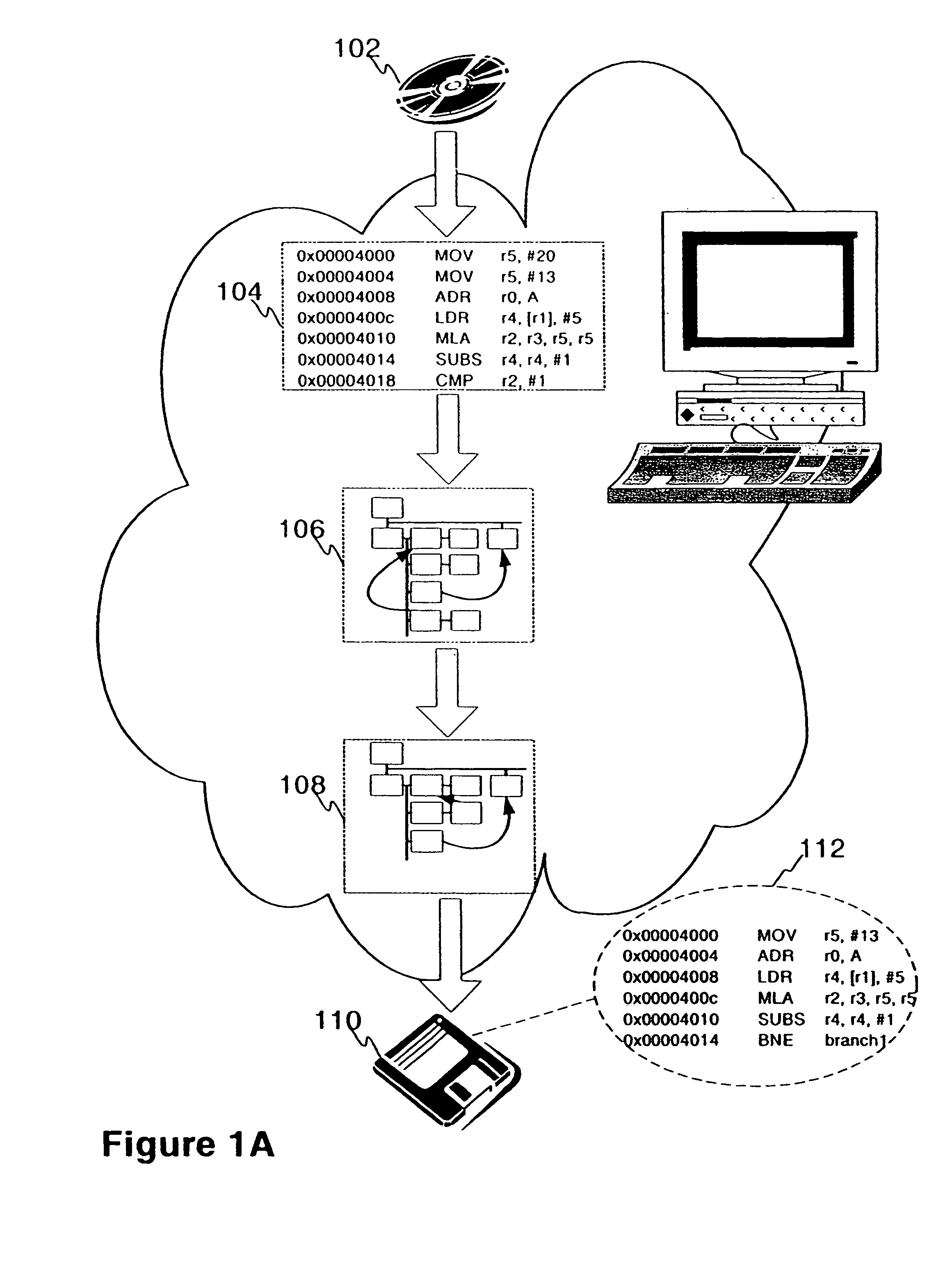
[0033]The concept of the invention is illustrated in FIG. 1A. The executable program is first loaded to the system of the invention for analysis from the storage medium 102. However, the program structure cannot be seen very clearly if at all by just examining the already compiled and linked one-part code in a debugger application 104. Thus, to ease the evaluation of the program flow a CFG is generated by propagating through the code and by determining the hierarchy of basic blocks 106 comprising the instructions and data that make up the overall executable. The CFG may then be exposed to code optimisation techniques 108 in order to achieve a more compact presentation of a functionally equivalent program 112 that can be then exported from the system for further use 110 by other devices.

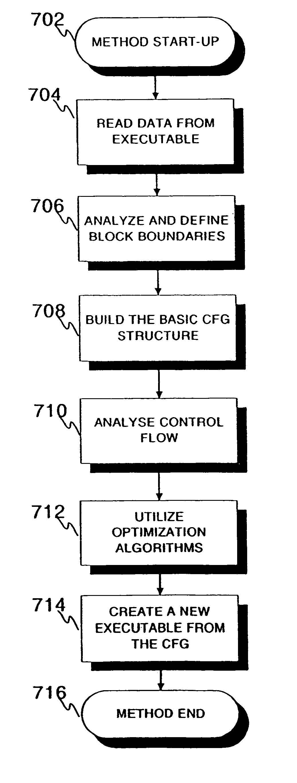
[0034]Still before going to the inner details of the embodiment, ATOM software, the method steps for creating a CFG according to the invention are explained with reference to FIG. 7A to facilitate fur...


PUM


Abstract

A method and a system for constructing a control flow graph (CFG, 106) from an executable computer program (104). The solution detects data intermixed with instructions and instruction set changes. The method includes the steps of defining block leader types specifying basic block boundaries in the program (104), building a CFG structure (106) according to the basic blocks found in the program, and adding control flow and addressing information to the CFG (106) by propagating through the basic blocks and internals thereof. The CFG (106) may be then optimised (108) and a compacted executable (112) created as a result.

Description

FIELD OF THE INVENTION[0001]The present invention relates generally to software engineering and program code representation and optimisation. In particular the invention concerns building of control flow graphs (CFG) from binary executable programs at post-link time.BACKGROUND OF THE INVENTION[0002]At the advent of modern computer programming era computer programs were typically so small in size that all the symbolic code for a single application could easily fit into a few screen shots mostly due to limitations set by reasonably low capacity memory chips used in low-end computers at that time. Memory space intended for free use by the applications could consist of some kilobytes only, thanks to high pricing of the memory chips. In the aforesaid type of context, it is evident that programming could be performed by a single person utilizing only a single source code file as program maximum size was very limited; no real benefits would have been gained from distributing either program...

Claims


Application Information

Patent Timeline
Patent Type & Authority Patents(United States)
IPC IPC(8): G06F9/45
CPCG06F8/433
Inventor BICSAK, ATTILAKISS, KOSFERENC, RUDOLFGYIMOTHY, TIBOR
Owner NOKIA CORP
Why Eureka
Try Eureka