
Methods and apparatus for minimizing evaporation of sample materials from multiwell plates

a multi-well plate and sample material technology, applied in the field of multi-well plate, can solve the problems of evaporation of samples, disturbed wells around the periphery or the corners of multi-well plates, too much air to flow to the wells, etc., and achieve the effect of reducing or substantially reducing the problem of excessive evaporation of sample materials

Active Publication Date: 2007-04-24
CALIPER TECH
View PDF14 Cites 124 Cited by
  • Summary
  • Abstract
  • Description
  • Claims
  • Application Information

AI Technical Summary

Benefits of technology

[0008]Novel methods and devices are disclosed for eliminating the problem of evaporation from sample wells of one or more multiwell plates, particularly when such multiwell plates are placed a stacked configuration as is typical in usage in HTS systems.
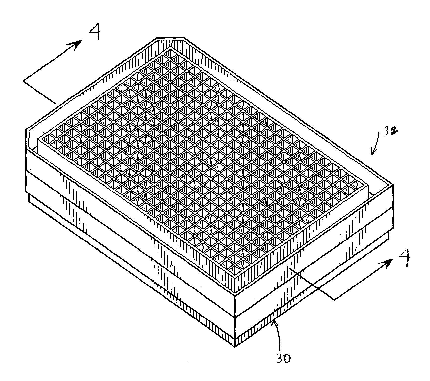
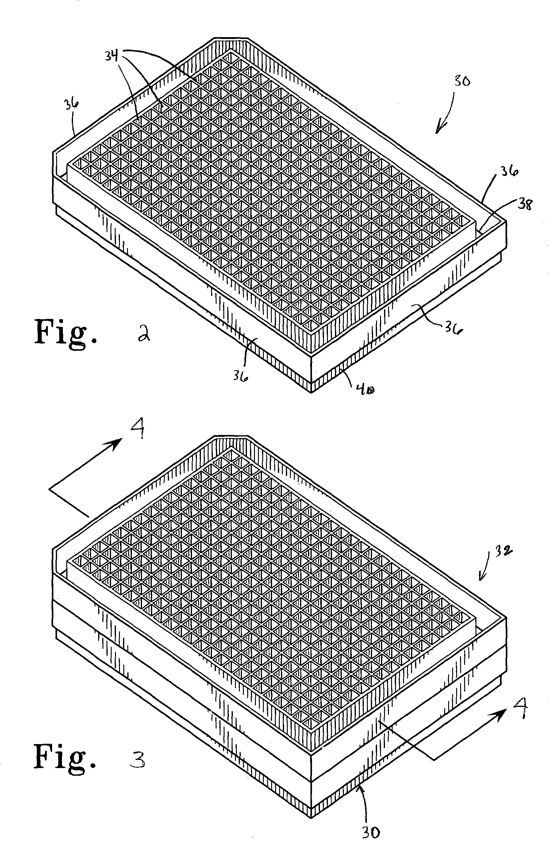
[0010]In a related aspect of the present invention, a method of reducing evaporation from one or more wells of at least a first multiwell plate which is configured to be positioned in a stacked configuration with at least one second multiwell plate is disclosed, which method includes providing at least the first multiwell plate with a plurality of wells and opposing side walls which extend around the plate and which define a ridge or channel spaced inwardly of the side walls and extending around the plate between the side walls and the plurality of wells; and at least partially filling the ridge with a liquid. In a preferred aspect of the invention, the second multiwell plate can include a downwardly extending flange which extends around a lower surface of the plate and which is configured to be removably received by the ridge of the at least first multiwell plate, such that when the second multiwell plate is positioned on the first multiwell plate, the flange extends at least partially into the ridge and contacts the liquid to thereby create a substantial evaporation barrier to prevent air exchange to the wells of the first multiwell plate and hence substantially eliminate evaporation of liquids contained therein when the plates are placed in a stacked configuration. The flange, when placed in the ridge of the first multiwell plate and made to contact the liquid contained therein, increases the vapor diffusion path length to the internal wells of the first multiwell plate and thereby slows evaporation of the buffer or other liquids contained within those wells. The flange could also be dimensioned to extend below the liquid level in the ridge, thus forming a “waterlock”, substantially preventing air movement to the peripheral wells of the first multiwell plate until the water in the ridge evaporates below the level of the flange of the second multiwell plate. The second multiwell plate may optionally not include a flange, such that when placed on top of the first multiwell plate, the second multiwell plate merely acts as a lid which helps to contain the liquid with the ridge of the first multiwell plate, which in some instances may be sufficient to substantially prevent or reduce evaporation of liquid sample contained with the wells of the multiwell plate(s).
[0011]The liquid introduced into the ridge can comprise water, buffer, or other suitable liquid which becomes a substantial evaporation barrier when the plates are stacked to substantially prevent air entrance to the wells to minimize evaporation of liquids in the wells. The liquid within the ridge must evaporate substantially completely before there will be substantial evaporation of the sample liquid contents within the wells of the multiwell plate. The step of at least partially filling the ridge with a liquid step can be performed either before or after the second multiwell plate is removably positioned on the first multiwell plate. A lower surface of the ridge of the first (and second) multiwell plate can optionally be provided with a plurality of spaced-apart ribs or small upwardly extending finger projections or the like which extend upwardly from the ridge and inwardly (e.g., perpendicular to the lengthwise dimension of the ridge) of the opposing side walls of the multiwell plate. The flanges or small projections in the ridge help to minimize sloshing of the liquid contained within the ridge and add structural strength and rigidity to the plate. When used, the upwardly extending ribs preferably have a height which is less than a height of the opposing side walls of the at least first multiwell plate such that a corresponding flange from a second multiwell plate can be placed within the ridge and made to contact the liquid contained therein when the first and second plates are placed in a stack. Further alternatively, the ridge can include a layer of at least one wicking material covering at least a portion of the ridge (or ribs or projections), such as a felt material, or a layer of absorbent material covering at least a portion of the ridge (or ribs or projections), that minimizes the tendency for liquid sloshing during operation of the system and which helps to further reduce evaporation by increasing the surface area of the liquid in the ridge which increases evaporation from the plate wells more effectively.
[0012]In a related aspect of the invention, a method of reducing evaporation from one or more wells of at least a first multiwell plate which is configured to be positioned in a stacked configuration with at least a second multiwell plate is provided, which method comprises providing at least a first multiwell plate having a plurality of wells and opposing side walls which extend around the plate and which define a ridge spaced inwardly of the side walls and extending around the plate between the side walls and the plurality of wells; providing at least a second multiwell plate having a downwardly extending flange which extends around a lower surface of the plate and which is configured to be removably received by the ridge of the at least first multiwell plate; at least partially filling the ridge with a liquid; and removably positioning said at least second multiwell plate on said at least first multiwell plate such that the flange extends at least partially into the ridge and contacts the liquid to thereby create a substantial evaporation barrier to prevent air entrance to the wells to minimize evaporation of sample liquids in the wells when the at least second multiwell plate is positioned on the at least first multiwell plate.
[0014]In accordance with the principles of the present invention, significant improvements over currently known and available multiwell plate assemblies are provided. Most importantly, the present invention eliminates or substantially reduces the problem of excessive evaporation of sample material that occurs in multiwell plates, especially when two or more plates are stacked on top of one another as they typically are for use in HTS systems. Sample liquid loss, particularly in the corner or peripheral wells of stacked multiwell plates, may be substantially reduced over current multiwell plate configurations.

Problems solved by technology

The inventor has recognized that currently available multiwell plates often permit too much air to flow to the wells from the external environment.
However, those wells around the periphery or the corners of the multiwell plate are disturbed by excess airflow from the external environment because those wells have an interface to the ambient environment where the plate handling equipment is located.
Excess air causes the evaporation of samples from wells, which is an issue for the performance of assays, particularly in HTS systems, where run times may be on the order of eight hours or more.
Samples must then either be replenished more frequently to compensate for evaporation, or the peripheral or corner wells filled with water or buffer and not used for the assays, which reduces the high throughput capabilities of the system.
However, in usage of HTS systems as described above, where multiwell plates are stacked one on top of another and must be readily and easily accessible by robotic systems and the like, the use of a separate lid or membrane to reduce evaporation is cumbersome and difficult to incorporate into the system.

Method used


Image

  • Methods and apparatus for minimizing evaporation of sample materials from multiwell plates
  • Methods and apparatus for minimizing evaporation of sample materials from multiwell plates
  • Methods and apparatus for minimizing evaporation of sample materials from multiwell plates

Examples


Embodiment Construction

[0024]The present invention provides novel methods and apparatus for minimizing evaporation of sample materials from multiwell plates, particularly when such plates are placed into a stacked configuration with one or more additional multiwell plates as is typical in usage in HTS systems, for example. It is to be understood, however, that the teachings of the present invention are in no way to be limited to their use in HTS systems as are generally described below, but can be used in any system or apparatus in which it is necessary to store one or more multiwell plates in a stacked (or unstacked) configuration prior to sampling of the sample components within the wells of the plates.

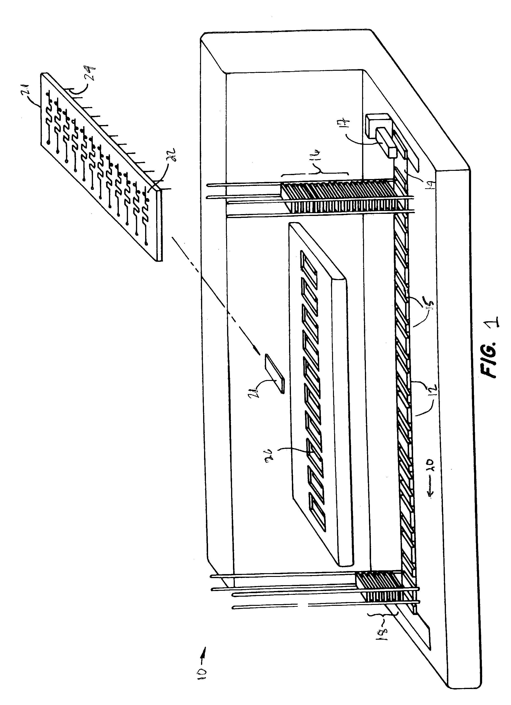
[0025]Referring first to FIG. 1, an exemplary HTS system 10 for screening large numbers of different compounds for their effects in a wide variety of chemical, and particularly biochemical systems, is shown. HTS system 10 generally manipulates samples by translating individual multiwell plates 12, which a...


PUM


Abstract

Methods and devices for reducing evaporation of sample materials from the wells of multiwell plates are disclosed which find particular utility when the plates are placed in a stacked configuration. An example of the methods includes providing at least a first multiwell plate which is configured to be placed in a stacked configuration with at least one second multiwell plate, the at least first multiwell plate having a plurality of wells for receiving sample material therein and opposing side walls which extend around the plate and which define a ridge spaced inwardly of the side walls and extending around the plate between the side walls and the plurality of wells, the method including at least partially filling the ridge with a liquid such as water or buffer solution. The ridge can include one or more ribs which extend upwardly from a lower surface of the ridge to help reduce sloshing of the liquid contained within the ridge and to add structural strength and rigidity to the multiwell plate. The second multiwell plate can be provided with a downwardly extending flange which extends around a lower surface of the plate and which is configured to be removably received by the ridge of the at least first multiwell plate such that when the second multiwell plate is removably positioned on top of the at least first multiwell plate in a stacked configuration, the flange extends at least partially into the ridge and contacts the liquid to thereby create a substantial evaporation barrier to minimize evaporation of sample liquids in the wells of the at least first multiwell plate.

Description

CROSS-REFERENCE TO RELATED APPLICATIONS[0001]This application claims the benefit of U.S. Provisional Patent Application No. 60 / 392,210, filed Jun. 28, 2002, which is incorporated herein by reference in its entirety for all purposes.FIELD OF THE INVENTION[0002]The present invention relates to multiwell plates for storing sample materials, and more particularly, to methods and apparatus for minimizing evaporation of sample materials from the wells of such plates, particularly where two or more multiwell plates are stacked one on top of another as they typically are in usage in high-throughput screening systems, for example.BACKGROUND OF THE INVENTION[0003]Recently, novel high-throughput screening (HTS) devices based on microfluidics technology have been developed which have the capability to rapidly assay compounds for their effects on various biological processes, including, for example, fluorogenic and mobility shift assays for multiple target classes including kinases, proteases an...

Claims


Application Information

Patent Timeline
IPC IPC(8): B01L3/00G01N1/00C12M1/22G01N21/00
CPCB01L3/50853C12M23/12B01L2200/025B01L2200/142Y10T436/25B01L2300/0829B01L2300/069C12M41/34
Inventor DONG, WESLEY BRYAN
Owner CALIPER TECH
Learn More