
Method of forming metal oxide and semimetal oxide

a technology of metal oxide and semimetal oxide, which is applied in the direction of coating, chemical vapor deposition coating, metallic material coating process, etc., can solve the problems of introducing intolerable defects into deposited materials, affecting the formation of metal oxide or semimetal oxide, and reducing the number of unsuitable reactions. , to achieve the effect of reducing unwanted reactions

Inactive Publication Date: 2007-04-24
MICRON TECH INC
View PDF2 Cites 3 Cited by
  • Summary
  • Abstract
  • Description
  • Claims
  • Application Information

AI Technical Summary

Benefits of technology

This approach effectively prevents the incorporation of OH groups, enhances the electrical performance of dielectric materials, and reduces the risk of side reactions, providing a more reliable method for forming metal and semimetal oxides in semiconductor devices.

Problems solved by technology

Nevertheless, such an imperfect monolayer is still a monolayer in the context of this document.
The second species might only bond to the first species and thus may also be self-limiting.
Accordingly, operating outside the traditional temperature and pressure ranges may risk formation of defective monolayers.
Such a condition may introduce intolerable defects into a deposited material.
Regardless of whether ALD, CVD or a combination of ALD and CVD is utilized to form metal oxide or semimetal oxide, there can be difficulties associated with the metal oxide or semimetal oxide formation.
One of the problems with conventional processes for forming metal oxide and semimetal oxide is that the processes frequently involve utilization of water as a reactant.
The amounts of water utilized in such deposition processes can cause incorporation of OH groups in deposited films which degrade electrical performance of dielectric materials.
In addition, water can be extremely difficult to remove from within a vacuum chamber.
Water within a vacuum chamber can cause unwanted side reactions (such as corrosion) relative to semiconductor structures associated with a substrate exposed to the water, and relative to the interior regions of a reaction chamber.

Method used


Image

  • Method of forming metal oxide and semimetal oxide
  • Method of forming metal oxide and semimetal oxide
  • Method of forming metal oxide and semimetal oxide

Examples


Embodiment Construction

[0027]This disclosure of the invention is submitted in furtherance of the constitutional purposes of the U.S. Patent Laws “to promote the progress of science and useful arts” (Article 1, Section 8).

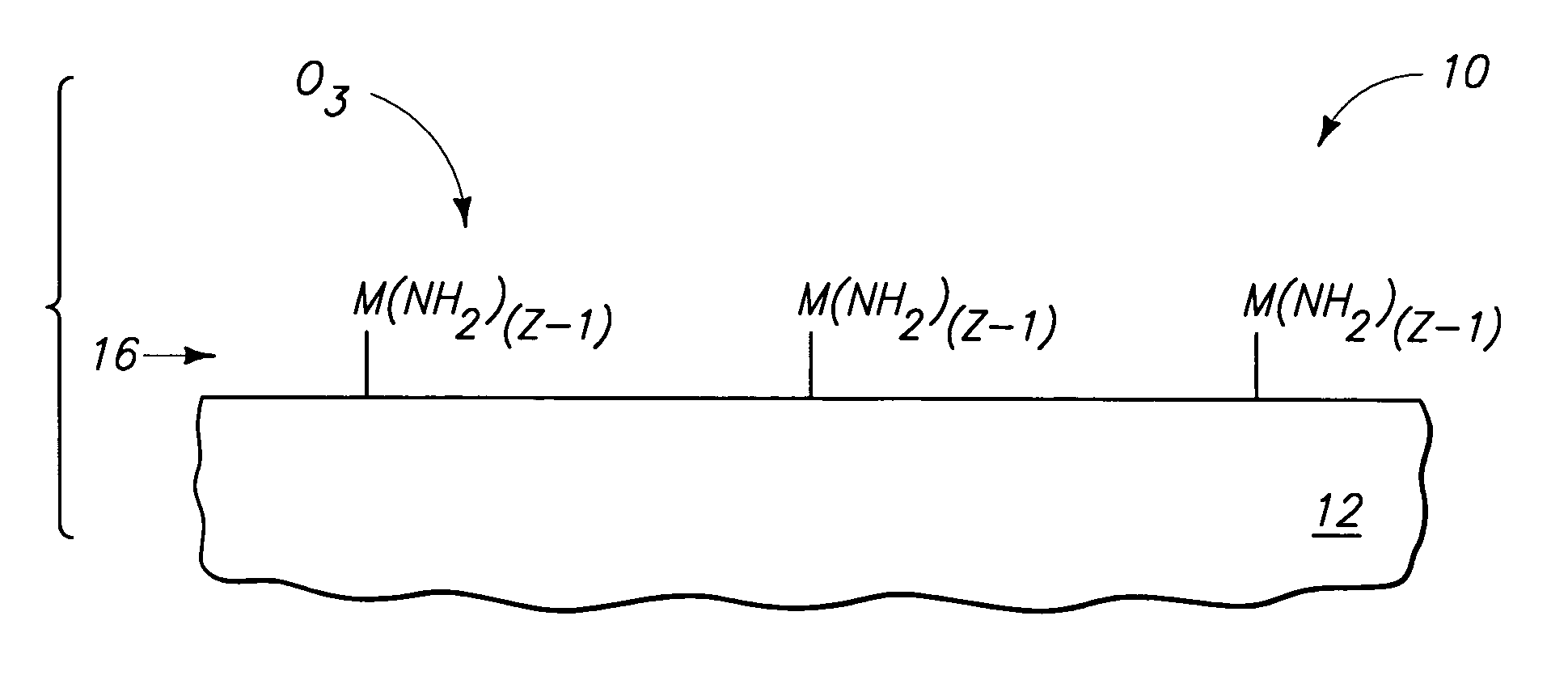
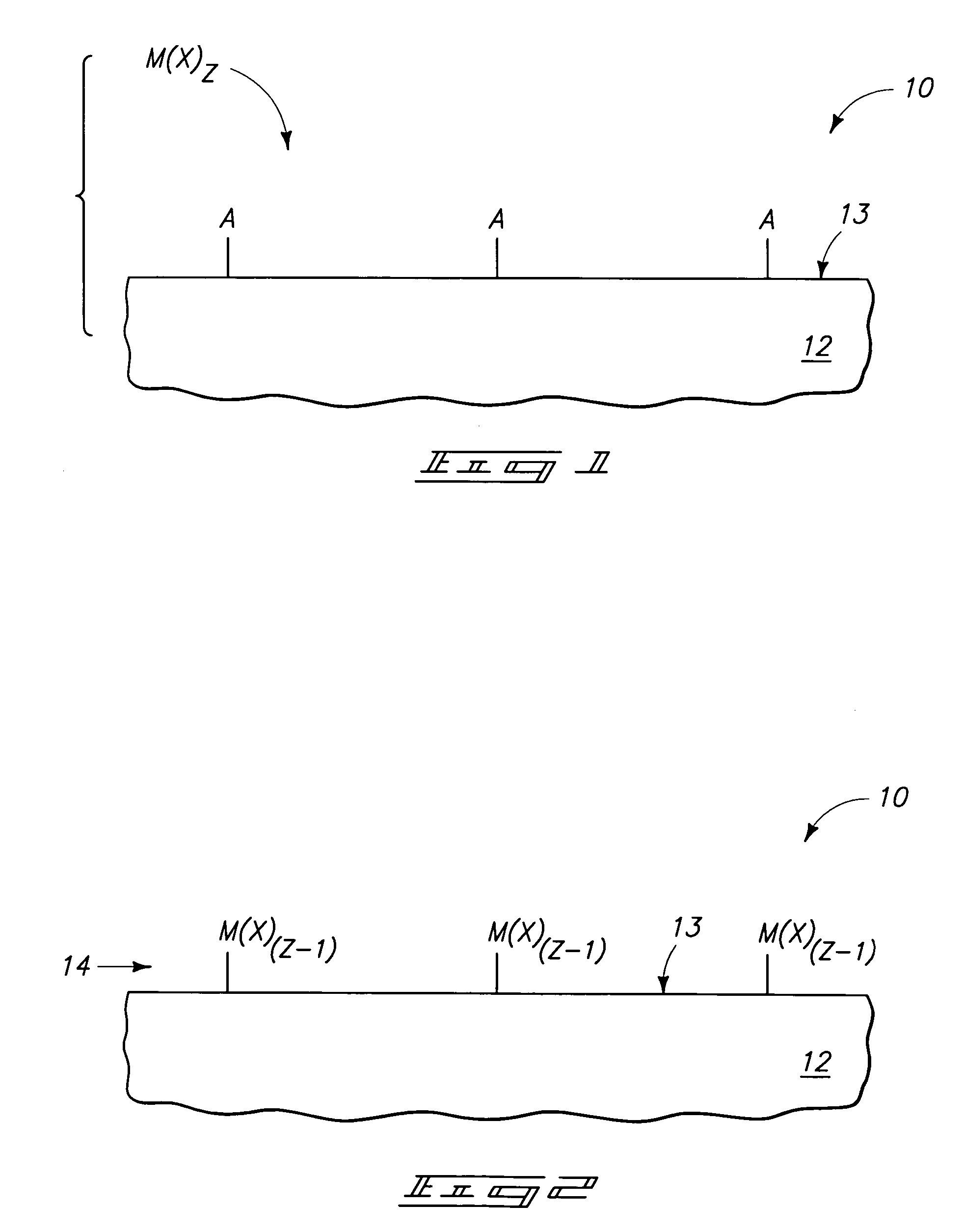
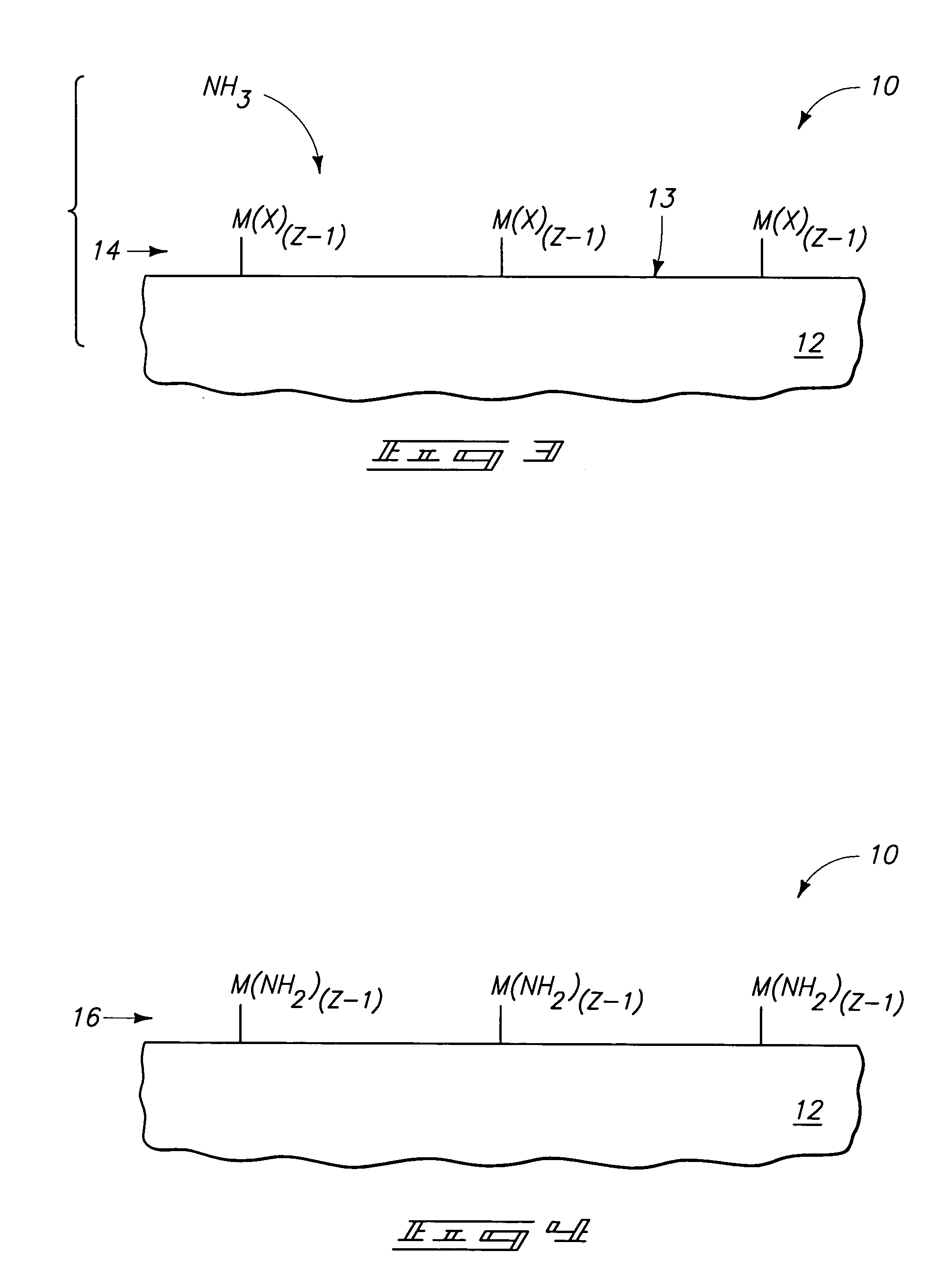
[0028]The invention includes methods of forming metal oxide in which at least one metal-and-halogen-containing material is formed over a semiconductor substrate surface, and then subjected to aminolysis followed by oxidation to convert the material to metal oxide. One of the reasons that water is utilized as an oxidant in prior art processes of converting metal chloride to metal oxide is that the metal chloride cannot be readily oxidized with oxidants other than water. One aspect of the present invention is a recognition that metal chlorides which are susceptible to hydrolysis are often also susceptible to aminolysis. Thus, aminolysis can be utilized to convert the metal chlorides to metal amines, which can then be oxidized with non-water oxidants to form metal oxides. The invention also ...


PUM

PropertyMeasurementUnit
dielectricaaaaaaaaaa
thickaaaaaaaaaa
pressureaaaaaaaaaa

Abstract

The invention includes methods of forming metal oxide and / or semimetal oxide. The invention can include formation of at least one metal-and-halogen-containing material and / or at least one semimetal-and-halogen-containing material over a semiconductor substrate surface. The material can be subjected to aminolysis followed by oxidation to convert the material to metal oxide and / or semimetal oxide. The aminolysis and oxidation can be separate ALD steps relative to one another, or can be conducted in a reaction chamber in a common processing step.

Description

TECHNICAL FIELD[0001]The invention pertains to methods of forming metal oxide and semimetal oxide.BACKGROUND OF THE INVENTION[0002]Metal oxides and semimetal oxides are commonly incorporated into semiconductor constructions. For instance, metal oxides and semimetal oxides can be utilized as dielectric materials in capacitor structures, and can be utilized as dielectric materials in other types of semiconductor devices.[0003]One of the methods that has been developed for forming metal oxide materials and semimetal oxide materials involves the utilization of a metal chloride precursor (such as, for example, hafnium chloride, titanium chloride, zirconium chloride, etc.) or semimetal chloride precursor (such as, for example, silicon chloride) to form a metal-chloride-containing layer or semimetal-chloride-containing layer over a substrate surface. The metal-chloride-containing layer or semimetal-chloride-containing layer is then exposed to water to convert the metal chloride or semimeta...

Claims


Application Information

Patent Timeline
Patent Type & Authority Patents(United States)
IPC IPC(8): H01L21/44
CPCC23C16/40C23C16/45525C23C16/45531C23C16/56H01L21/02164H01L21/02181H01L21/02186H01L21/02205H01L21/02211H01L21/0228H01L21/3141H01L21/31604H01L21/31608H01L21/31637H01L21/31641H01L21/31645H01L21/02189
Inventor MARSH, EUGENE P.
Owner MICRON TECH INC
Learn More