4.6 mm small arms ammunition

a small arms and ammunition technology, applied in the field of ammunition, can solve the problems of steel not readily deformable, high rate of angular acceleration, and substantial wear on the barrel, and achieve the effect of reducing the coefficient of friction, easy deformation, and easy formation into the desired shap

Active Publication Date: 2007-05-01
RUAG AMMOTECH
View PDF20 Cites 19 Cited by
  • Summary
  • Abstract
  • Description
  • Claims
  • Application Information

AI Technical Summary

Benefits of technology

[0018]For a warshot ammunition nature to be used in combat conditions, steel is a suitable material, as it is inexpensive and can be readily formed into the desired shape, e.g. by a cold-forming process. Tungsten is another possible material because hardness is an important characteristic for target defeat, as are alloys of tungsten, and tungsten carbide.
[0019]The projectile is coated with copper or a copper alloy, which is more readily deformable than the material of the projectile body itself, and which may have a lower coefficient of friction. These factors can lead to a reduced engraving force with correspondingly lower barrel wear and higher muzzle velocity.
[0020]A coating thickness between 0.07 mm and 0.3 mm may be suitable. Such a coating could conveniently be applied by electroplating or by chemical deposition.

Problems solved by technology

The deformation of the projectile, its travel along the barrel effectively as a force fit to the rifling, the high linear acceleration imparted by the gun propellant on firing, and the consequent high rate of angular acceleration and associated force acting between rifling and projectile all contribute to substantial wear on the barrel.
However, steel is not readily deformable, and causes unacceptable barrel wear.
This latter solution is practical, but results in a bullet having a relatively expensive construction.
This is a very significant disadvantage since small arms ammunition is consumed in large quantities, and the market for such ammunition is highly competitive.
As a result, the bullet disclosed in U.S. Pat. No. 5,686,693 will lack the desirable hardened target penetration capability.

Method used


Image

  • 4.6 mm small arms ammunition
  • 4.6 mm small arms ammunition
  • 4.6 mm small arms ammunition

Examples


Embodiment Construction

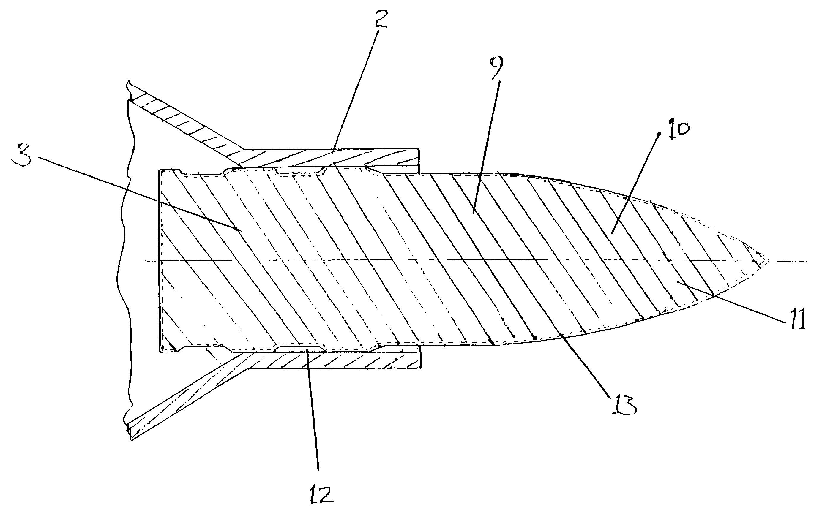
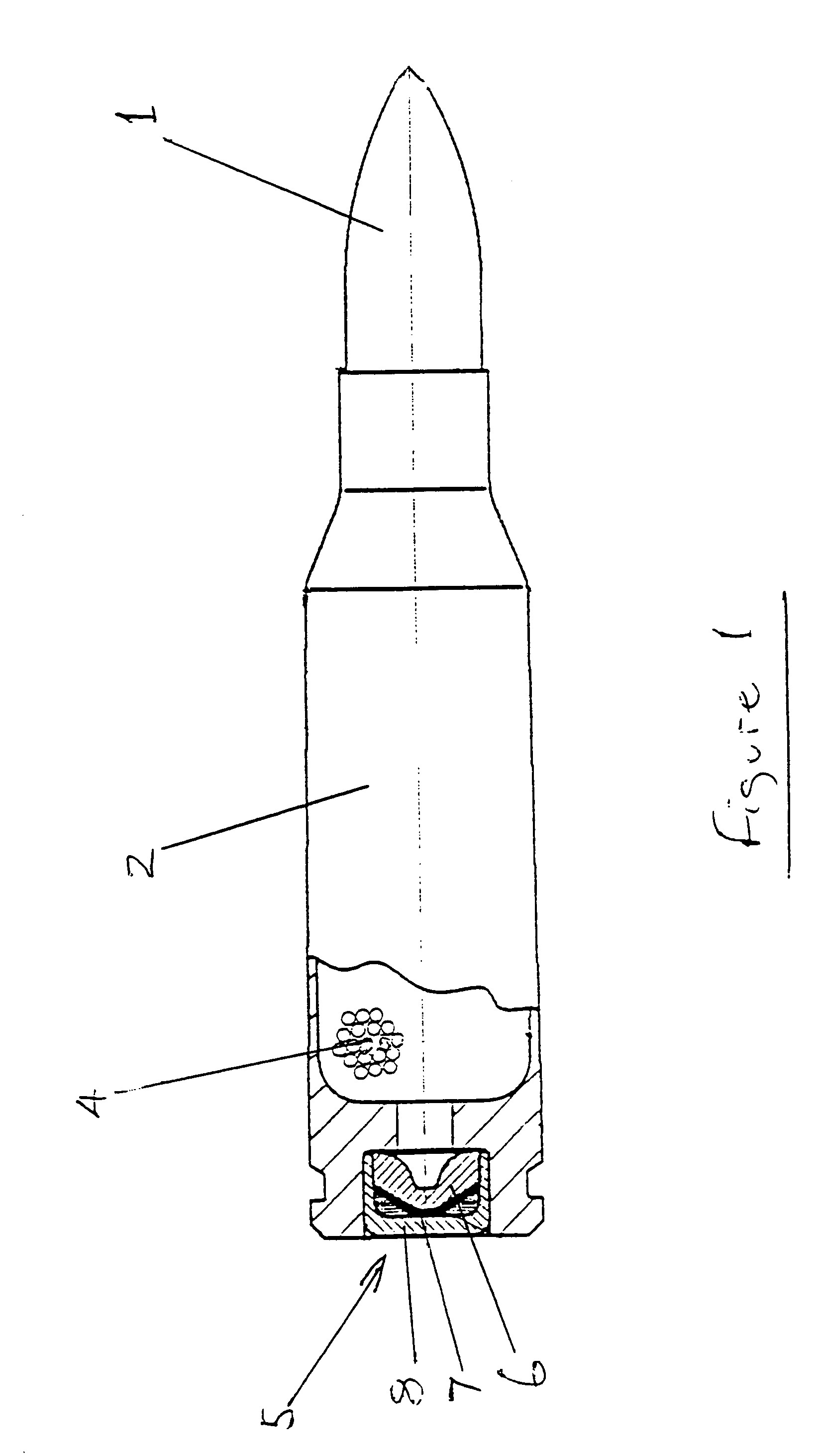
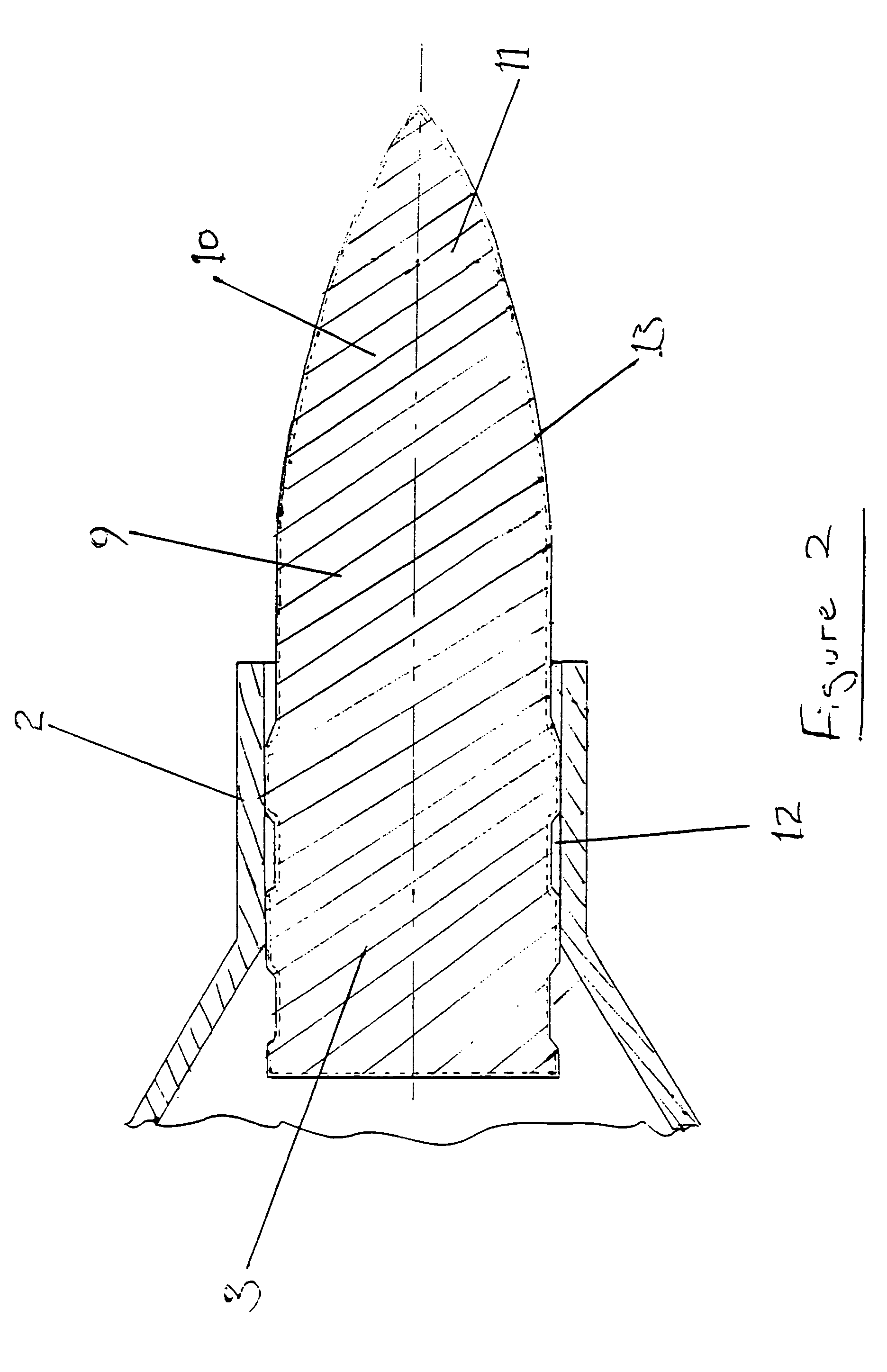
[0028]As shown in FIG. 1, a round of small arms ammunition comprises a projectile 1, and a brass cartridge case 2 assembled thereto. The rearward portion 3 (FIG. 2) of the projectile is received within the forward part of the cartridge case, and the two components are held together by friction. The cartridge case contains a quantity of gun propellant material 4, and a percussion primer cap 5 comprising an anvil 6, a quantity of primary propellant 7 and a closure cap 8 which is received as a press fit in a recess in the rear end face of the cartridge case.

[0029]The projectile body is of elongate form and is cold formed from steel having a Vickers Hardness of at least 550 (using a 10 kg load). It can subsequently be given a heat treatment to provide the desired hardness or other physical properties. The projectile comprises a body portion 9 of substantially cylindrical form. The projectile also has a nose portion 10 forward of the portion 9, the nose portion 10 having an ogival forwar...


PUM

PropertyMeasurementUnit
thicknessaaaaaaaaaa
thicknessaaaaaaaaaa
thicknessaaaaaaaaaa

Abstract

A round of ammunition for firing from a gun having a rifled barrel, especially a small arms weapon. The projectile (1) forming a part of the round is of steel or other material having a Vickers Hardness value not less than 550, and has a coating (13) of copper or copper alloy. The projectile has a forward body portion (9) which has a diameter similar to that of the lands of the rifling, and a rearward body portion (3) having a diameter which is similar to the diameter defined by the roots of the rifling grooves. The coating (13) is of a thickness not less than the depth of the said rifling grooves, so that the rifling engraves the coating but does not significantly engrave the underlying steel or other hard material. The advantages associated with a hard projectile material are thus obtained without substantially increasing barrel wear.

Description

[0001]This application is the US national phase of international application PCT / GB2004 / 001111, filed in English on 16 Mar. 2004, which designated the US. PCT / GB2004 / 001111 claims priority to GB Application No. 0307272.5, filed 27 Mar. 2003. The entire contents of these applications are incorporated herein by reference.BACKGROUND OF THE INVENTION[0002]1. Field of the Invention[0003]This invention relates to ammunition for use in a weapon having a rifled barrel, and especially to an improved form of projectile for small arms ammunition.[0004]2. Discussion of Prior Art[0005]When a projectile is fired from a rifled barrel, the projectile must deform as it travels along the barrel so that material forming part of the projectile is forced into the spaces between the lands forming the rifling. This process is called engraving, and causes a spin to be imparted to the projectile by virtue of the longitudinal twist of the rifling.[0006]The deformation of the projectile, its travel along the ...

Claims


Application Information

Patent Timeline
Patent Type & Authority Patents(United States)
IPC IPC(8): F42B12/04F42B12/78F42B12/74F42B12/82
CPCF42B12/74F42B12/82
Inventor BOOTH, DEREKSMITH, ADRIAN DAVIDASHLEY, ROBERT
Owner RUAG AMMOTECH
Why Eureka
Try Eureka