Advanced high efficiency, ultra-low emission, thermochemically recuperated reciprocating internal combustion engine

a reciprocating, high-efficiency technology, applied in the direction of machines/engines, combustion-air/fuel-air treatment, sustainable manufacturing/processing, etc., can solve the problems of significant energy waste, the need for ready availability of hydrogen, etc., to reduce the emission of unburned fuel, and increase the engine combustion efficiency

Active Publication Date: 2007-05-01
GAS TECH INST
View PDF22 Cites 78 Cited by
  • Summary
  • Abstract
  • Description
  • Claims
  • Application Information

AI Technical Summary

Benefits of technology

[0011]It is another object of this invention to provide a method and apparatus for reducing the emissions produced by conventional reciprocating internal combustion engines.
[0012]It is yet a further object of this invention to provide a method and apparatus for increasing the efficiency of a reciprocating internal combustion engine over conventional such engines.
[0015]These and other objects of this invention are addressed by an apparatus comprising an advanced thermochemical recuperation system, also referred to herein as a thermochemical recuperator, and a reciprocating internal combustion engine, in which apparatus the heat and steam recovered from the waste energy of the engine are used not only for increasing the efficiency of the engine, but also for fuel reforming by the thermochemical recuperator, thereby obviating the need to provide steam and heat from external sources. The reformed fuel contains significant amounts of hydrogen, which increases the engine combustion efficiency, resulting in lower unburned fuel emissions. The amount of inert gas and water vapor in the reformed fuel also decreases NOx emissions significantly. In addition, the engine is able to operate at lower combustion temperatures, which decreases the closed-cycle losses, resulting in increased thermal efficiency. The thermochemical recuperator can be employed to reform either liquid or gaseous fuels, although liquid fuel reforming may require an evaporator to evaporate the liquid fuel prior to mixing with the steam. The thermochemical recuperator can be incorporated into conventional reciprocating spark-ignition or compression-ignition engines, HCCI (lean) and fuel-rich reciprocating engines with afterburners, Miller-cycle engines, and reciprocating engines with a turbocharger, supercharger, or natural aspiration. The thermochemical recuperator can also be incorporated into coal gasifier and industrial furnace systems to increase systems efficiencies and decrease emissions. In remote areas, a water recovery system can be used to capture water from the engine exhaust for use as feed water for the thermochemical recuperator.
[0016]An additional benefit of using the thermochemical recuperator with an internal combustion engine in accordance with this invention is that lower quality fuels may be used, thereby providing the opportunity for further savings in operating costs. In a stationary engine, further emissions reductions may be attained if, for example, either a non-selective catalytic reduction (NSCR) system or three way catalyst is used together with the thermochemical recuperator. Due to cleaner combustion, the maintenance cost of the engine may even be decreased. In addition to new installations, this system may be incorporated into existing diesel or natural gas engines at a relatively low retrofit cost. With the development of new designs and new catalysts, such as nickel-tin (Ni / Sn), the cost of the thermochemical recuperator itself also may be significantly reduced compared to conventional systems.

Problems solved by technology

However, one problem associated with the use of hydrogen in such applications is the requirement for ready availability of the hydrogen in a form suitable for use therein.
Thus, one issue which needs to be addressed is the production of H2 in a manner which satisfies the availability requirements.
In a typical reciprocating engine system, a significant amount of energy is wasted.

Method used


Image

  • Advanced high efficiency, ultra-low emission, thermochemically recuperated reciprocating internal combustion engine
  • Advanced high efficiency, ultra-low emission, thermochemically recuperated reciprocating internal combustion engine
  • Advanced high efficiency, ultra-low emission, thermochemically recuperated reciprocating internal combustion engine

Examples


Embodiment Construction

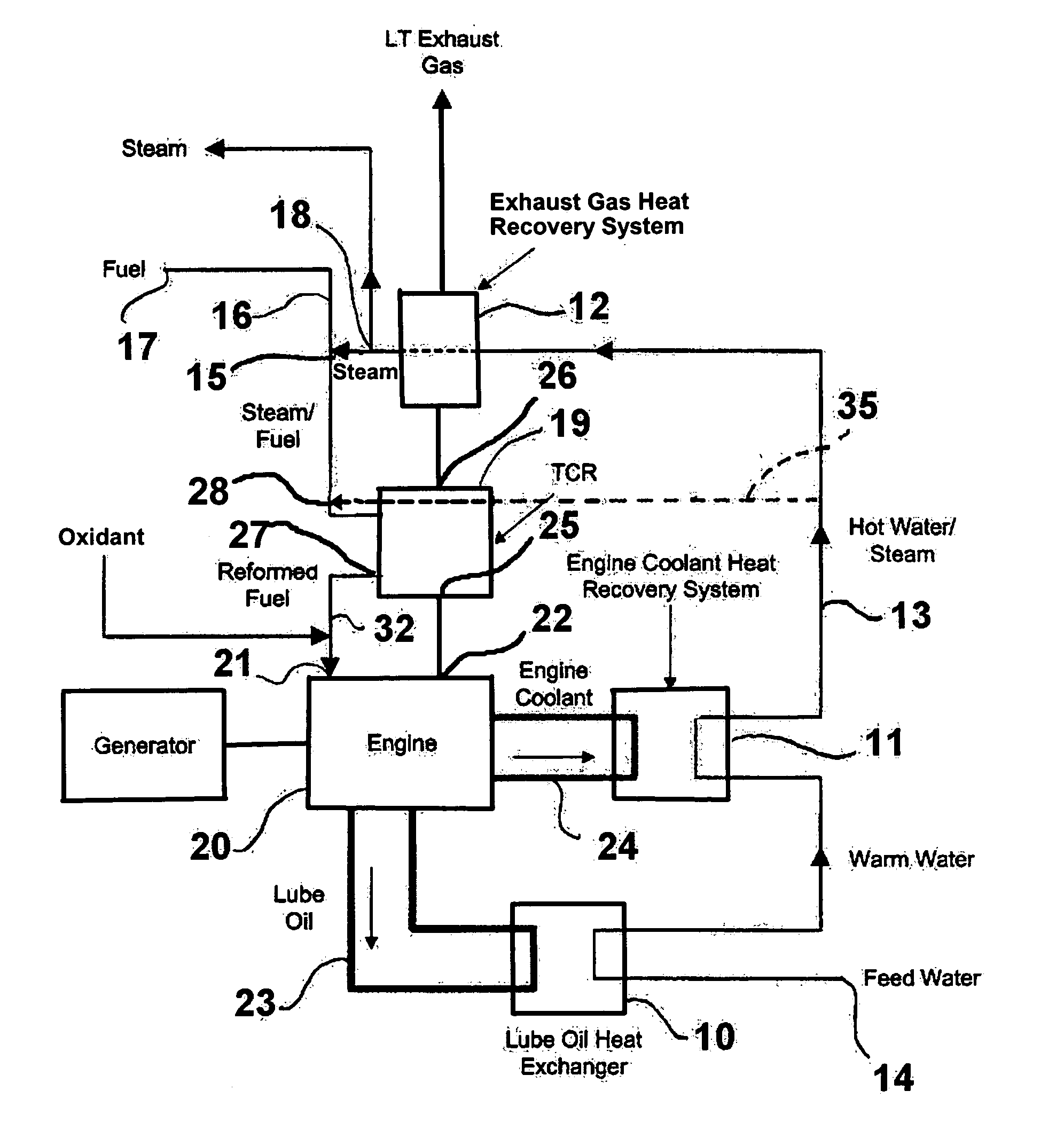
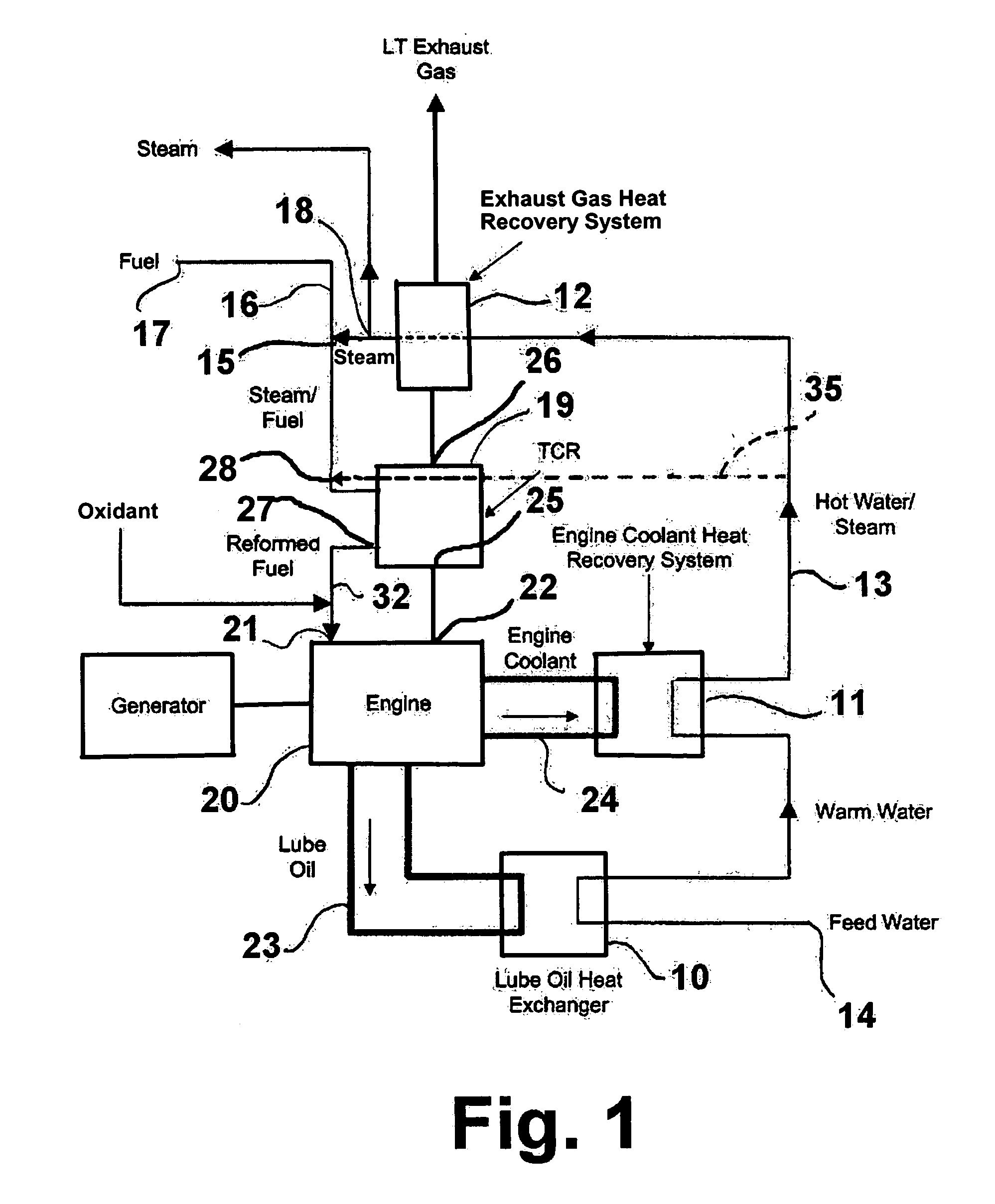
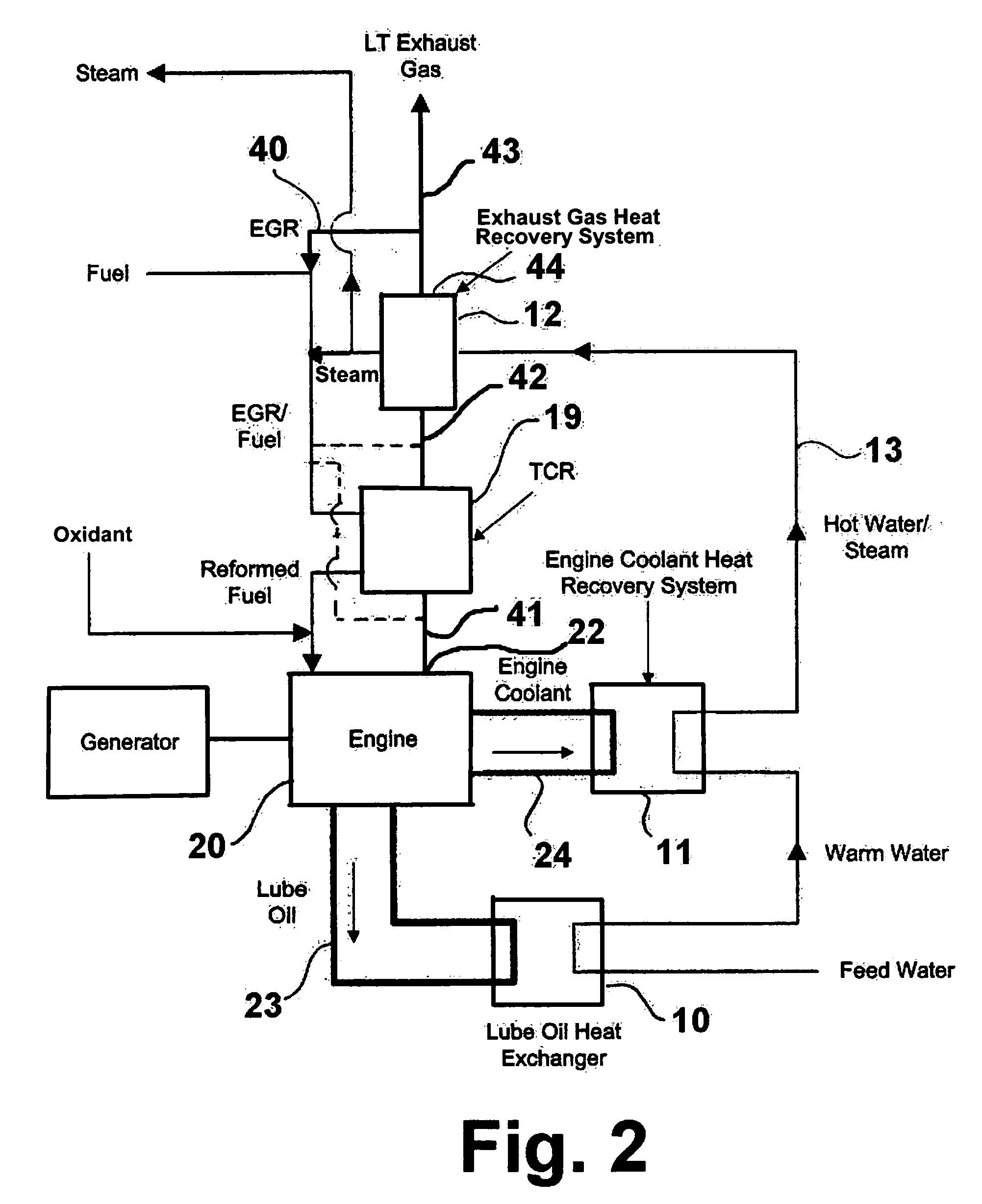
[0037]The advanced thermochemical recuperator (TCR) of this invention is an innovative technology that can be retrofitted to, or be newly installed in, a wide range of internal combustion (IC) engines, such as stationary reciprocating engines and gas turbines. As previously stated, the thermochemical recuperator in accordance with one embodiment of this invention uses steam and heat recovered from waste energy such as exhaust energy and closed-cycle heat losses from the engine to reform natural gas or other reformable fuels to a H2-enriched fuel suitable for use in the engines. This endothermic reaction increases the energy content of the fuel significantly, resulting in higher fuel economy. The thermochemical recuperator of this invention is suitable for reforming a variety of liquid and gaseous fuels.

[0038]Hydrogen provides numerous benefits to the combustion of a reciprocating internal combustion (IC) engine due to its faster flame speed, shorter quenching distance, etc. Thus, us...


PUM

PropertyMeasurementUnit
reforming temperatureaaaaaaaaaa
temperaturesaaaaaaaaaa
compression ratioaaaaaaaaaa

Abstract

An apparatus including a reciprocating internal combustion engine and a thermochemical recuperator in which a fuel is reformed. The thermochemical recuperator is heated by exhaust gases from the reciprocating internal combustion engine and steam for the reforming process is produced by passing feed water through an engine lubricating oil heat exchanger, an engine cooling system heat recovery system and an exhaust gas heat recovery system arranged in series.

Description

BACKGROUND OF THE INVENTION[0001]1. Field of the Invention[0002]This invention relates to an internal combustion engine and a method for operation of an internal combustion engine. This invention also relates to thermochemical recuperators and the use of thermochemical recuperators as fuel reformers for providing reformed fuel to a reciprocating internal combustion engine.[0003]2. Description of Related Art[0004]Natural gas is the most abundant energy source available after coal. People are looking for more ways to use natural gas as fuel because it is inexpensive and burns very cleanly relative to other energy sources, particularly with respect to coal. In addition, because natural gas is in abundant supply, using more natural gas as an energy source provides a means for reducing dependence on imported foreign oils.[0005]Over the past several years, fuel cells, which typically use hydrogen (H2) as a fuel, have been receiving a substantial amount of attention due to their almost emi...

Claims


Application Information

Patent Timeline
Patent Type & Authority Patents(United States)
IPC IPC(8): F02B43/08C01B3/34F01N5/02F01P3/20F01P11/08F02B37/00F02M21/06F02M25/12F02M33/00
CPCC01B3/34F01P3/20F02B37/00F02M21/06F02M25/0228F02M25/12F02M33/00F02D19/0644F02D19/0671F02M21/0206F02M21/0215F02M25/035F01N5/02Y02T10/36F01N2240/14F01N2240/30F01P2060/04F02B2275/32Y02E20/14Y02T10/121Y02T10/144Y02T10/142Y02T10/16Y02T10/32Y02P20/10Y02P20/129Y02T10/12Y02T10/30
Inventor KWEON, CHOL-BUMKHINKIS, MARK J.NOSACH, VILYAM G.ZABRANSKY, ROBERT F.
Owner GAS TECH INST
Why Eureka
Try Eureka