Lobed joint draft inducer blower

a blower and joint technology, applied in the direction of machines/engines, stators, liquid fuel engines, etc., can solve the problems of compromising the air flow efficiency of the blower housing and generating noise, so as to reduce the noise of the air flow, facilitate maximum air flow efficiency, and high efficiency

Active Publication Date: 2007-05-01
REGAL BELOIT AMERICA
View PDF27 Cites 43 Cited by
  • Summary
  • Abstract
  • Description
  • Claims
  • Application Information

AI Technical Summary

Benefits of technology

[0011]The present invention provides a draft inducer blower for high efficiency furnaces, including a blower housing which facilitates maximum air flow efficiency through the blower housing while reducing air flow noises. The blower housing generally includes a housing body and housing cover which define an exhaust transition therebetween, which transitions the air flow from the circular main cavity of the blower housing to the blower housing outlet. The housing body and housing cover are attached to one another via a lobed joint along the exhaust transition, and each include complementary, smoothly contoured inner surfaces to facilitate smooth air flow through the exhaust transition toward the outlet. Additionally, the housing body and housing cover include cooperating cutoff surfaces which form a broadly radiused cutoff within the blower housing to reduce or eliminate the blade pass noise associated with contact of the air flow from the impeller with the cutoff.
[0012]In particular, the housing body and housing cover are attached to one another along a primary joint line which extends around the outer peripheries thereof, and are also attached to one another along a secondary, lobed joint line which extends along the exhaust transition and slopes upwardly in the axial direction toward the exhaust outlet. The foregoing construction allows the inner surfaces of the housing body and housing cover to be molded as smoothly contoured and complementary surfaces in the area of the exhaust transition to facilitate smooth air flow through the exhaust transition toward the outlet. In this manner, the air flow does not encounter obstructions in the exhaust transition which would induce turbulence in the air flow, generating noise and compromising the air flow efficiency of the blower housing.
[0013]The housing body and housing cover each include broadly radiused cutoff portions which, when the housing cover is joined to the housing body, cooperate with one another via a pin-and-hole joint to define a broadly radiused cutoff to reduce or eliminate blade pass noise associated with the cutoff. Additionally, the pin-and-hole joint between the cutoff portions of the housing body and housing cover aids in locating the housing body with respect to the housing cover, and also forces the mutually facing surfaces of the housing body and housing cover into tight engagement with one another to assure minimum edge mismatches due to part warpage, for example, such that no protruding edges cause turbulence in the air flow.
[0014]Advantageously, the internal and external features of the housing body are configured such that the housing body may be formed according to a molding process using a pair of molds which may be separated from the housing body along the Z-axis direction after the plastic material of the housing body cures. Only one additional mold is needed to form the circular outlet of the housing body, which mold may conveniently take the form of a short, cylindrical mold which is separated from the housing body in the radial or X- or Y-axis direction after the plastic material of the housing body cures. In a similar manner, the features of the housing cover are configured to allow the housing cover to be formed via a molding process including a pair of molds which may be separated from the housing cover in the axial direction after the plastic material of the housing cover cures. In this manner, manufacture of the blower housing from plastic material, via a molding process such as injection molding, is simplified.

Problems solved by technology

In this manner, the air flow does not encounter obstructions in the exhaust transition which would induce turbulence in the air flow, generating noise and compromising the air flow efficiency of the blower housing.

Method used


Image

  • Lobed joint draft inducer blower
  • Lobed joint draft inducer blower
  • Lobed joint draft inducer blower

Examples


Embodiment Construction

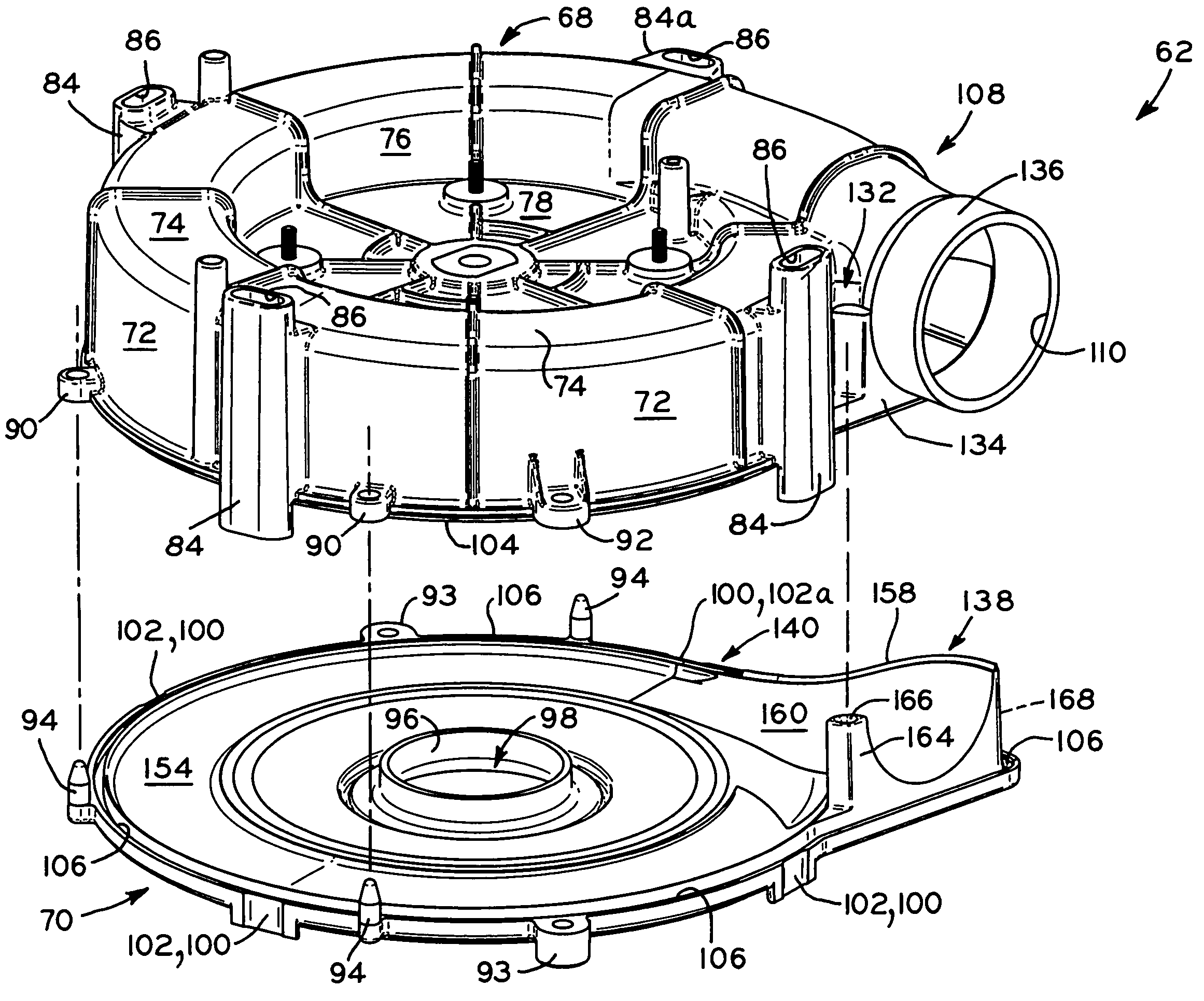
[0033]Referring first to FIGS. 5–7, a blower 60 for a high efficiency furnace according to the present invention is shown. Blower 60 generally includes blower housing 62, electric motor 64 mounted to blower housing 62, and an impeller (FIGS. 7 and 8), described below, mounted to the output shaft 66 of motor 64 and disposed within blower housing 62. Blower housing 62 generally includes a first housing member or housing body 68, and a second housing member or housing cover 70. Housing body 68 and housing cover 70 may be formed of metal or plastic according to an injection molding process, for example. Suitable plastics for housing body 68 and housing cover 70 include polypropylene or other thermoplastics. Housing body 68 includes a generally cylindrical outer wall 72, an annular top wall 74, an inner wall 76, and a circular, recessed wall 78. Motor 64 is attached to recessed wall 78 by a plurality of fasteners 80 which pass through mounting flanges 82 of motor 64 and into holes in rec...


PUM


Abstract

A draft inducer blower for high efficiency furnaces, including a blower housing which facilitates maximum air flow efficiency through the blower housing while reducing air flow noises. The blower housing generally includes a housing body and housing cover which define an exhaust transition therebetween, which transitions the air flow from the circular main cavity of the blower housing to the blower housing outlet. The housing body and housing cover are attached to one another via a lobed joint along the exhaust transition, and each include complementary, smoothly contoured inner surfaces to facilitate smooth air flow through the exhaust transition toward the outlet. Additionally, the housing body and housing cover include cooperating cutoff surfaces which form a broadly radiused cutoff within the blower housing to reduce or eliminate the blade pass noise associated with contact of the air flow from the impeller with the cutoff.

Description

BACKGROUND OF THE INVENTION[0001]1. Field of the Invention[0002]The present invention relates to air moving devices, and in particular, to blowers of the type which are used with high efficiency (e.g., 90% or higher efficiency) furnaces for drawing air from outside of a building into the furnace to support combustion and to expel combustion exhaust products outside of the building. More particularly, the present invention relates to a blower which provides more efficient air flow through the blower housing with decreased blower noise.[0003]2. Description of the Related Art[0004]In high efficiency furnaces, standard chimney air-draw effects are not sufficient to assure the required air flow through the furnace heat exchangers, and therefore, high efficiency furnaces utilize draft inducer blowers to provide sufficient air flow through the furnace. In particular, the blowers of high efficiency furnaces pull flue gases through the furnace heat exchangers and then push the flue gases out...

Claims


Application Information

Patent Timeline
Patent Type & Authority Patents(United States)
IPC IPC(8): F04D29/44
CPCF04D29/422F04D29/626
Inventor LYONS, LESLIE A
Owner REGAL BELOIT AMERICA
Why Eureka
Try Eureka