Elongated medical device with functional distal end

a medical device and distal end technology, applied in the field of medical devices, can solve the problems of undesirable inserting of the larger outer tube distal end into the heart wall, difficult to restore the blood flow to the coronary artery, etc., and achieve the effect of lessening the likelihood of a shaft distal end, increasing resistance to penetrating the heart wall, and increasing the radial exten

Inactive Publication Date: 2007-05-01
BOSTON SCI SCIMED INC
View PDF80 Cites 16 Cited by
  • Summary
  • Abstract
  • Description
  • Claims
  • Application Information

AI Technical Summary

Benefits of technology

[0009]The present invention includes devices for performing percutaneous myocardial revascularization (PMR) that can lessen the likelihood of a shaft distal end penetrating undesirably into the myocardium. In one application, PMR devices are used to penetrate the endocardium and myocardium to a controlled depth. One group of devices according to the present invention includes an inner shaft having a therapeutic tip, for example, a distal cutting tip. The inner shaft can be disposed within an outer tube or shaft lumen, and the outer shaft can be disposed within the lumen of a guide catheter. Preferably, the myocardium. is penetrated by the cutting tip of the inner shaft but not by any larger profile outer shafts or tubes disposed about the inner shaft. The outer shaft distal region preferably has a first configuration having a small radial extent or profile allowing disposition of the outer shaft within a small guide catheter. The outer shaft distal region preferably also has a second configuration having a larger radial extent or profile for presentation against the endocardium. While having the larger profile, the outer tube distal end has increased resistance to penetrating the heart wall. The larger surface presented to the heart wall while in the radially expanded position forms a more atraumatic distal end for the outer tube distal end.
[0010]The outer tube distal end can have an atraumatic distal hood or tip that is formed of an elastic material that can be benignly forced against an obstacle such as the heart chamber inner wall, the endocardium. The atraumatic hood allows passage of the therapeutic tip therethrough to contact the heart wall. The atraumatic hood preferably has a sufficiently small profile so as to fit within an enclosing guide catheter in a first configuration. In one embodiment, the atraumatic hood is sufficiently elastic to longitudinally foreshorten and radially expand to attain a larger profile or radial extent when forced against the endocardium. The radially enlarged hood presents a larger transverse surface area to the heart wall and inhibits penetration of the heart wall by the outer shaft distal end. In one embodiment, the atraumatic hood has a bulbous shape and has a distal-most orifice for receiving the cutting tip of a slidably disposed inner therapeutic shaft.
[0012]Another outer shaft atraumatic distal end or stop includes a spring wound about the outside of the outer shaft distal region. The spring preferably has a constrained configuration when contained within an enclosing guide catheter. When advanced distally from the guide catheter, the spring preferably expands radially to a second, unconstrained configuration having a larger profile. The larger profile can present a hindrance to penetration of the endocardium by the distal end of the outer shaft. After use of any inner therapeutic shaft, the outer shaft can be retracted within a guide catheter, again constraining the distal spring and reducing the radial extent. In one embodiment, the spring is formed as a helical coil. In another embodiment, the spring is formed as a ribbon or clock spring disposed about a relatively short length of the outer shaft.
[0013]One device outer shaft includes an atraumatic distal region formed as an inflatable member having a small, uninflated profile and a large, inflated profile. The shaft can include an inflation lumen and the inflatable member can include an inflatable balloon having an interior in fluid communication with the inflation lumen. The distal inflatable member can be inserted uninflated within a guide catheter for delivery to a target site such as the endocardium. After advancing the distal inflatable member from a guide catheter, inflation fluid can be supplied through the inflation lumen and into the inflatable member, thereby increasing the radial extent of the inflatable member. The inflated member or balloon can present a larger distal transverse surface area, which presents an inhibition to penetration of the endocardium by the outer shaft distal end. One device has a dual lumen shaft with side-by-side lumens. Another device has an inflation lumen coaxially disposed about an inner lumen which can be used for delivery of a therapeutic inner shaft.

Problems solved by technology

In some patients, the number of lesions are so great, or the locations so remote in the coronary vasculature, that restoring coronary artery blood flow to the heart is difficult.
While inserting a cutting tip into the heart wall may be desirable, inserting the larger outer tube distal end into the heart wall may be undesirable.

Method used


Image

  • Elongated medical device with functional distal end
  • Elongated medical device with functional distal end
  • Elongated medical device with functional distal end

Examples


Embodiment Construction

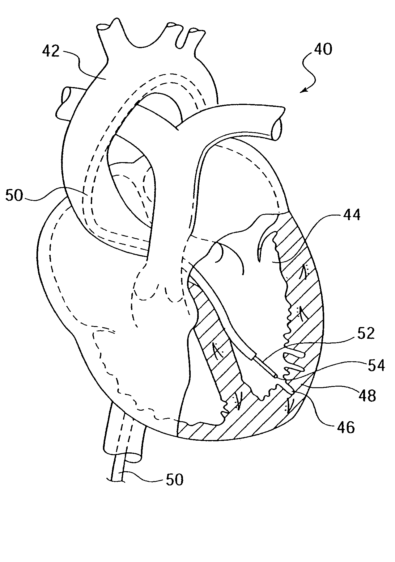
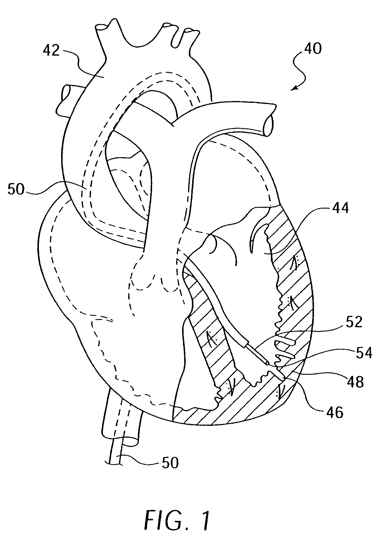
[0055]FIG. 1 illustrates a human heart 40 having a guide catheter 50 inserted through the aortic arch 42 and into the left ventricle 44. Guide catheter 50 is shown having a therapeutic catheter 52 extending therethrough terminating in a therapeutic catheter therapeutic tip 54. Therapeutic tip 54 can be used to form a plurality of holes 46 in left ventricle wall 48. Therapeutic tip 54 can be used to form holes in order to stimulate a healing, response as well as to inject angiogenic substances such as VEGF and other factors well-known in the art. As can be seen from inspection of FIG. 1, the depth of holes 46 in left ventricle wall 48 are important as the holes should optimally not penetrate through the entire wall thickness of the myocardium. As further explained below, therapeutic catheter 52 is often not directly disposed within guide catheter 50. In particular, therapeutic catheter 52 may be disposed within an enclosing outer tube coaxially disposed between therapeutic catheter 5...


PUM


Abstract

An elongate medical device that may be used for performing medical procedures on a patient is provided. This elongate medical device may include a first member having an elongated configuration, a second member pivotally coupled to the first member at a pivot area of the first member, and a manipulation member extending through either a first lumen or a second lumen of the first member. The second member of this device may have a first region on one side of the pivot area and a second region on a different side of the pivot area. The medical device may also include a third member slidable within one of the lumens of the first member.

Description

CROSS-REFERENCE TO RELATED APPLICATIONS[0001]This application is a Continuation of application Ser. No. 10 / 379,591, filed Mar. 6, 2003, now U.S. Pat. No. 6,767,338 which is a Continuation of application Ser. No. 09 / 695,527, filed Oct. 24, 2000, now U.S. Pat. No. 6,582,400 both of which are included herein in their entirety by reference.FIELD OF THE INVENTION[0002]The claims of the present invention are directed towards medical devices. More specifically, the claims of the present invention are related to catheters, endoscopes, and other medical devices with function distal ends that may be used to perform medical procedures within the body of a patient.BACKGROUND OF THE INVENTION[0003]A number of techniques are available for treating cardiovascular disease such as cardiovascular bypass surgery, coronary angioplasty, coronary atherectomy, and stent placement. These techniques are generally performed to bypass or open lesions in coronary vessels to restore patency and increase blood f...

Claims


Application Information

Patent Timeline
Patent Type & Authority Patents(United States)
IPC IPC(8): A61M5/178A61B17/00A61B17/22A61B17/34
CPCA61B17/3478A61M25/0069A61B2017/00247A61B2017/22069A61B2017/22077A61B2017/348A61B2017/3488A61B2018/00392A61B2018/00738A61B2019/306A61B2218/002A61M25/10A61M2025/1093A61B2090/036
Inventor HAWK, MATTHEWLARSON, SCOTTMICKLEY, TIMOTHY J.HARRIS, CHAD
Owner BOSTON SCI SCIMED INC
Why Eureka
Try Eureka