Piezoelectric thin-film resonator and filter using the same

a thin-film resonator and filter technology, applied in piezoelectric/electrostrictive/magnetostrictive devices, piezoelectric/electrostriction/magnetostriction machines, semiconductor devices, etc., can solve the problems of reducing the efficiency of the cavity, affecting the performance of the cavity, and generating unnecessary spurious components, etc., to achieve sufficient membrane strength, suppress adverse effects, and small irregular characteristics

Active Publication Date: 2007-05-01
TAIYO YUDEN KK
View PDF7 Cites 8 Cited by
  • Summary
  • Abstract
  • Description
  • Claims
  • Application Information

AI Technical Summary

Benefits of technology

[0012]More specifically, the present invention provides a piezoelectric thin-film resonator and a filter equipped with the same that show little irregularity in characteristics, by employing a structure that makes it possible to suppress the adverse affects caused by the lateral mode waves and to achieve a sufficient strength of the membrane and excellent productivity of the cavity.

Problems solved by technology

Therefore, the piezoelectric thin-film resonator and the filter using the same are attracting attention.
However, in addition to the thickness-extensional wave, the above-mentioned piezoelectric thin-film resonator has undesired waves of the lateral mode that are propagated in parallel with the electrode surface, and are reflected by the interfaces or an edge of the cavity.
This adversely generates an unnecessary spurious component in the impedance characteristics of the resonator, or a ripple in the passband of the filter.
This causes a problem in an application.
However, the proposed structures and configurations degrade the strength of the membrane or the productivity of the cavity to the contrary.
Unfortunately, any one of Documents 1, 2, and 3 has a structurally unbalanced symmetry, and the force applied to the membrane is not equal.
Thus, the membrane is easily distorted and damaged.
This results in a serious problem that resonance characteristics and filter characteristics show large irregularity.
If the size of the cavity is much bigger than that of the overlapping region, the membrane will be easily damaged.
Thus, it is not recommended.
In addition, the productivity of the cavities disclosed in Documents 1 through 3 is not good.
This results in stray capacitance between the overlapping extensions of the upper electrode and the lower electrode, and degrades the electromechanical coupling coefficient (K2).

Method used


Image

  • Piezoelectric thin-film resonator and filter using the same
  • Piezoelectric thin-film resonator and filter using the same
  • Piezoelectric thin-film resonator and filter using the same

Examples


first embodiment

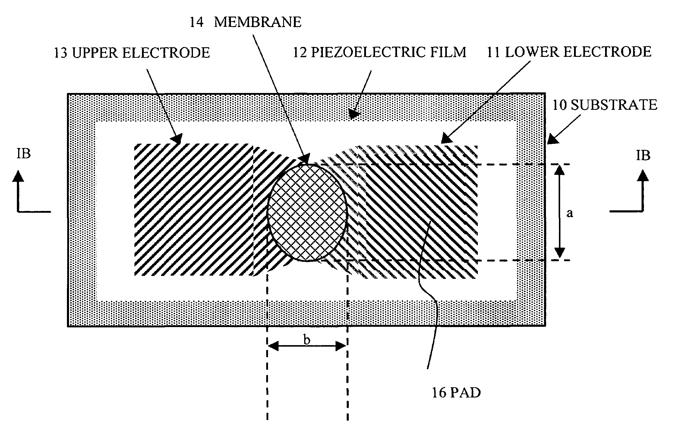
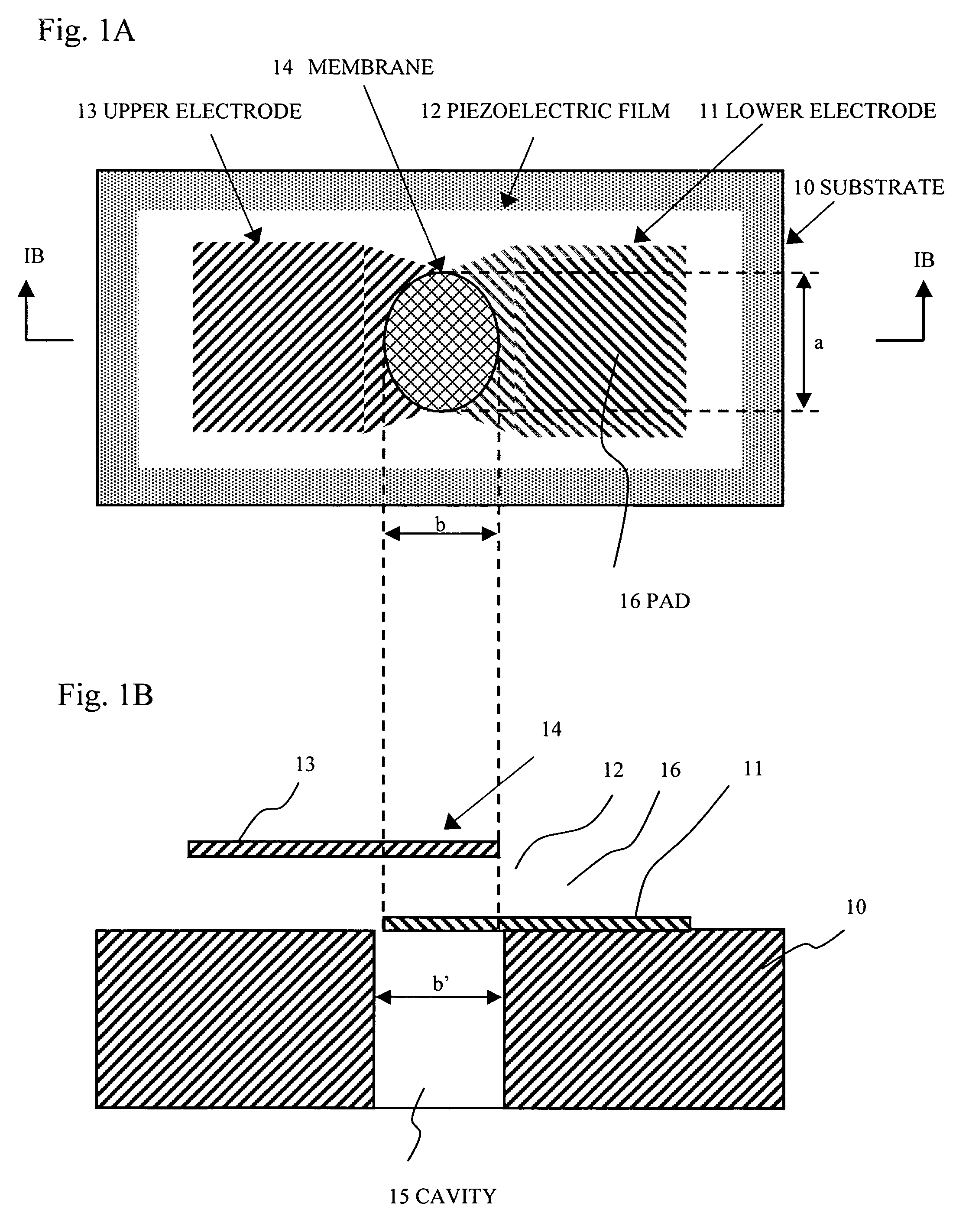
[0035]FIG. 1A shows a plain view of a piezoelectric thin-film resonator in accordance with a first embodiment of the present invention. FIG. 1B shows a cross-section view taken along a line IB—IB shown in FIG. 1A. The piezoelectric thin-film resonator shown in FIGS. 1A and 1B includes a substrate 10, a lower electrode 11 arranged on the substrate 10, a piezoelectric film 12 arranged on the lower electrode 11, and an upper electrode 13 arranged on the piezoelectric film 12. The electrode 10 is made of, for example, silicon (Si). The lower electrode 11 is made of a conductive material having a double layer structure of, for example, ruthenium (Ru) and chromium (Cr). The layer of ruthenium is arranged on a main surface of the substrate 10. The piezoelectric film 12 is made of a piezoelectric material, for example, aluminum nitride (AlN). The upper electrode 13 is made of a conductive material having a single layer structure of ruthenium (Ru), for example. For example, the piezoelectric...

second embodiment

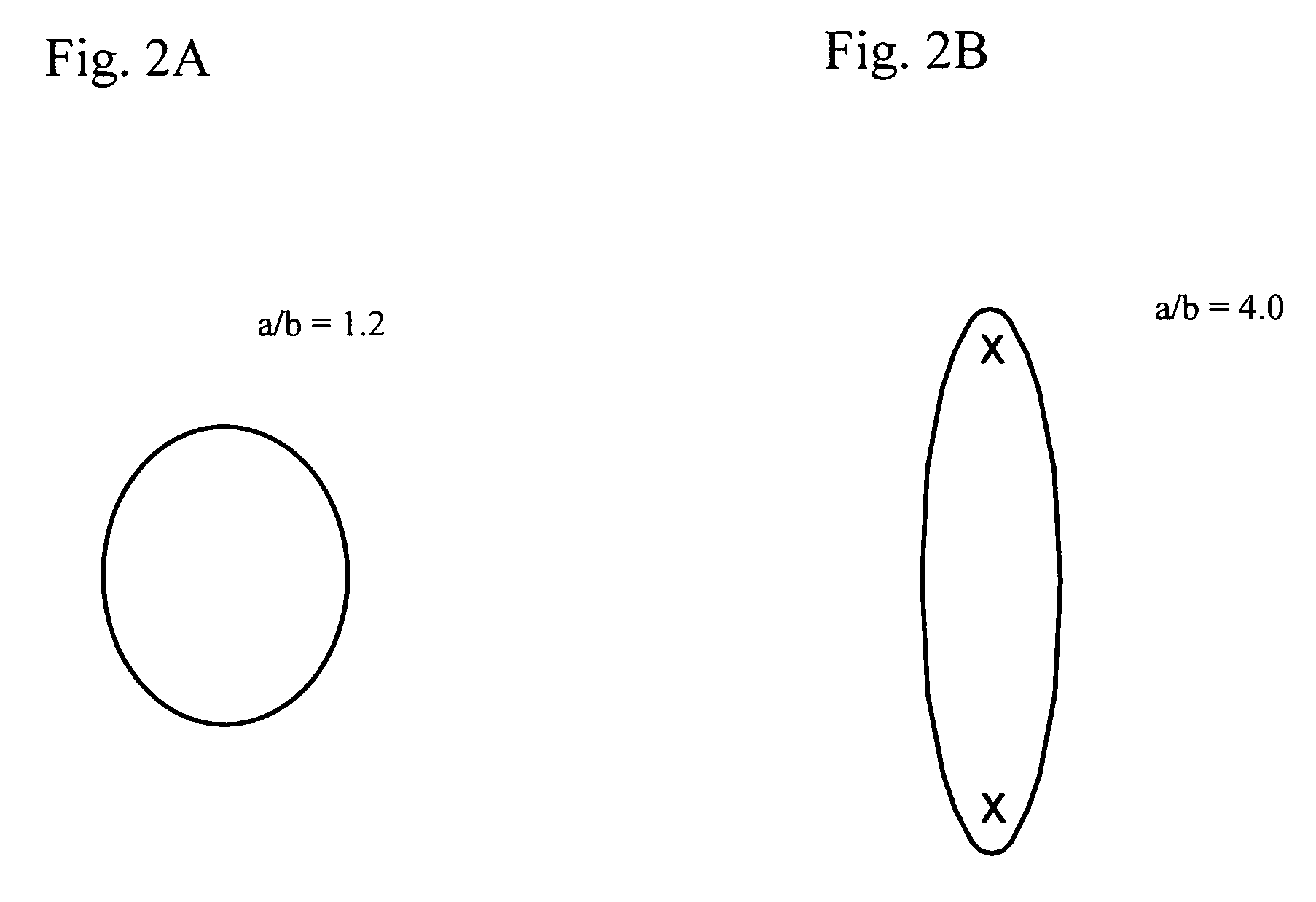
[0043]A description will now be given of a second embodiment of the present invention. The second embodiment has a specific relationship between the shape of elliptical shape and the size of the membrane 14 used in the first embodiment. The inventors evaluated any influence on characteristics, when altering the ratio of b′ / b where b is the length of the sub axis of the elliptical shape in the membrane 14 where the upper electrode 13 overlaps with the lower electrode 11, and b′ is the length of the sub axis of the cavity 15, as shown in FIGS. 1A and 1B. In the second embodiment, the size b is fixed and only the size b′ is altered. The region where the upper electrode 13 overlaps with the lower electrode 11 through the dielectric film 12 has an elliptical shape such that a=60.2 μm and b=50.2 μm (a / b=1.2). The cap 15 has an elliptical shape that meets a / b=1.2. FIG. 6 shows a b′ / b dependency of the resonant resistance. When b′ / b is too small, the resonance characteristic is degraded bec...

third embodiment

[0044]A description will now be given of a third embodiment of the present invention. The third embodiment has a specific relationship between the direction of the current flowing through a piezoelectric thin-film resonator and the axis direction of the elliptical shape in the membrane 14 where the upper electrode 13 overlaps with the lower electrode 11 through the dielectric film 12. The inventors studied the relationship for three piezoelectric thin-film resonators shown in FIGS. 7A, 7B, and 7C. FIG. 7A shows a case where the sub axis is parallel to the current direction (hereinafter referred to type A). FIG. 7B shows a case where the main axis is parallel to the current direction (hereinafter referred to type B). FIG. 7C shows a case where the main and sub axes are slanted by 45 degrees to the current direction (hereinafter referred to type C). The types A and B have substantially symmetric shapes in which the upper electrode 13 and the lower electrode 11 are symmetric about an a...


PUM


Abstract

A piezoelectric thin-film resonator includes a substrate, a lower electrode arranged on the substrate, a piezoelectric film arranged on the lower electrode, and an upper electrode arranged on the piezoelectric film. A region in which the upper electrode overlaps with the lower electrode through the piezoelectric film has an elliptical shape, and a condition such that 1<a / b<1.9 is satisfied where a is a main axis of the elliptical shape, and b is a sub axis thereof.

Description

BACKGROUND OF THE INVENTION[0001]1. Field of the Invention[0002]This invention generally relates to piezoelectric thin-film resonator and a filter using the same.[0003]2. Description of the Related Art[0004]Wireless devices as represented by mobile telephones have spread rapidly, and there has been an increasing demand for a downsized and lightweight resonator and a filter equipped with the same. A dielectric substance and a surface acoustic wave have been used extensively so far; however, the piezoelectric thin-film resonator and the filter equipped with the same have excellent high frequency characteristics, can be downsized, and can be incorporated into a monolithic circuit. Therefore, the piezoelectric thin-film resonator and the filter using the same are attracting attention.[0005]The piezoelectric thin-film resonator may be categorized into FBAR (Film Bulk Acoustic Resonator) type and SMR (Solidly Mounted Resonator) type. The FBAR type includes main components on a substrate f...

Claims


Application Information

Patent Timeline
Patent Type & Authority Patents(United States)
IPC IPC(8): H01L41/08H01L41/09H01L29/82H01L41/187H03H9/13H03H9/15H03H9/17H03H9/54H03H9/56H03H9/58
CPCH03H9/02133H03H9/132H03H9/174H03H9/564H03H9/568H03H9/15
Inventor NISHIHARA, TOKIHIROYOKOYAMA, TSUYOSHISAKASHITA, TAKESHIIWAKI, MASAFUMIMIYASHITA, TSUTOMU
Owner TAIYO YUDEN KK
Why Eureka
Try Eureka