
Antireflection film, and image display device

an anti-reflection film and image display technology, applied in the field of anti-reflection film and image display device, can solve the problems of uneven interference and appearence, and achieve the effect of less interference and low reflectan

Inactive Publication Date: 2007-05-01
FUJIFILM CORP
View PDF9 Cites 22 Cited by
  • Summary
  • Abstract
  • Description
  • Claims
  • Application Information

AI Technical Summary

Benefits of technology

[0007]An object of the present invention is to provide an antireflection film having a low reflectance and less interference unevenness, or an image display device using this antireflection film.

Problems solved by technology

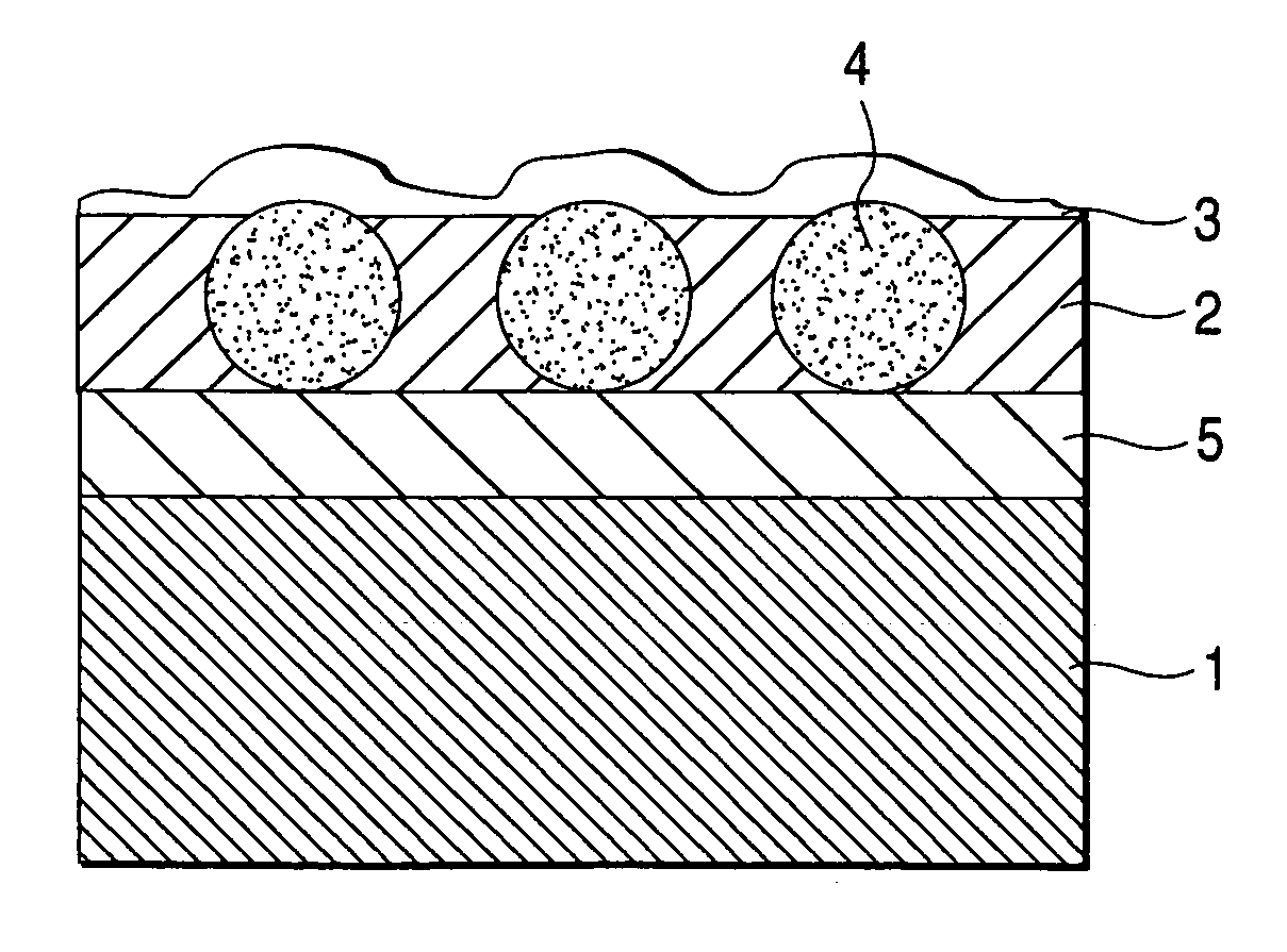
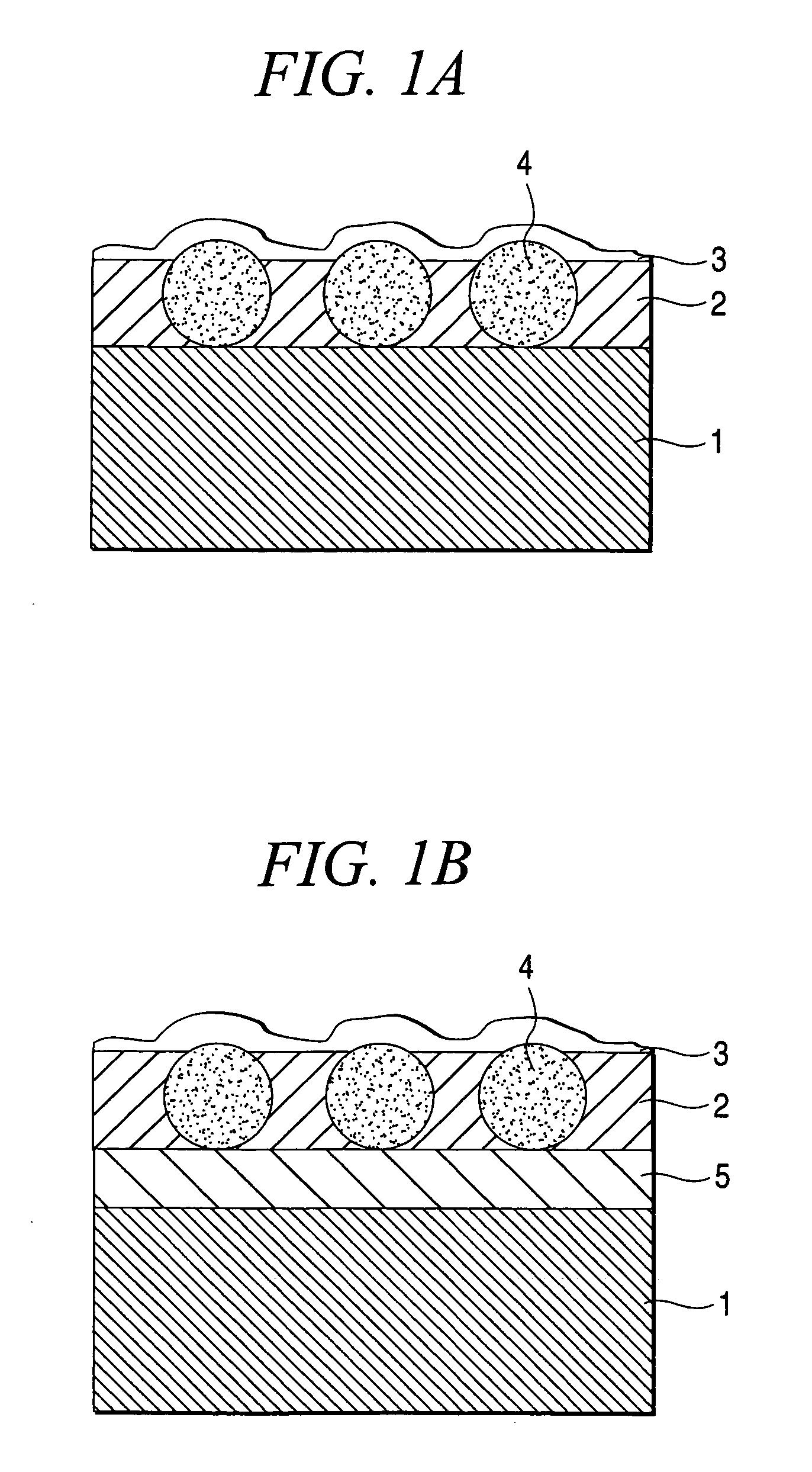
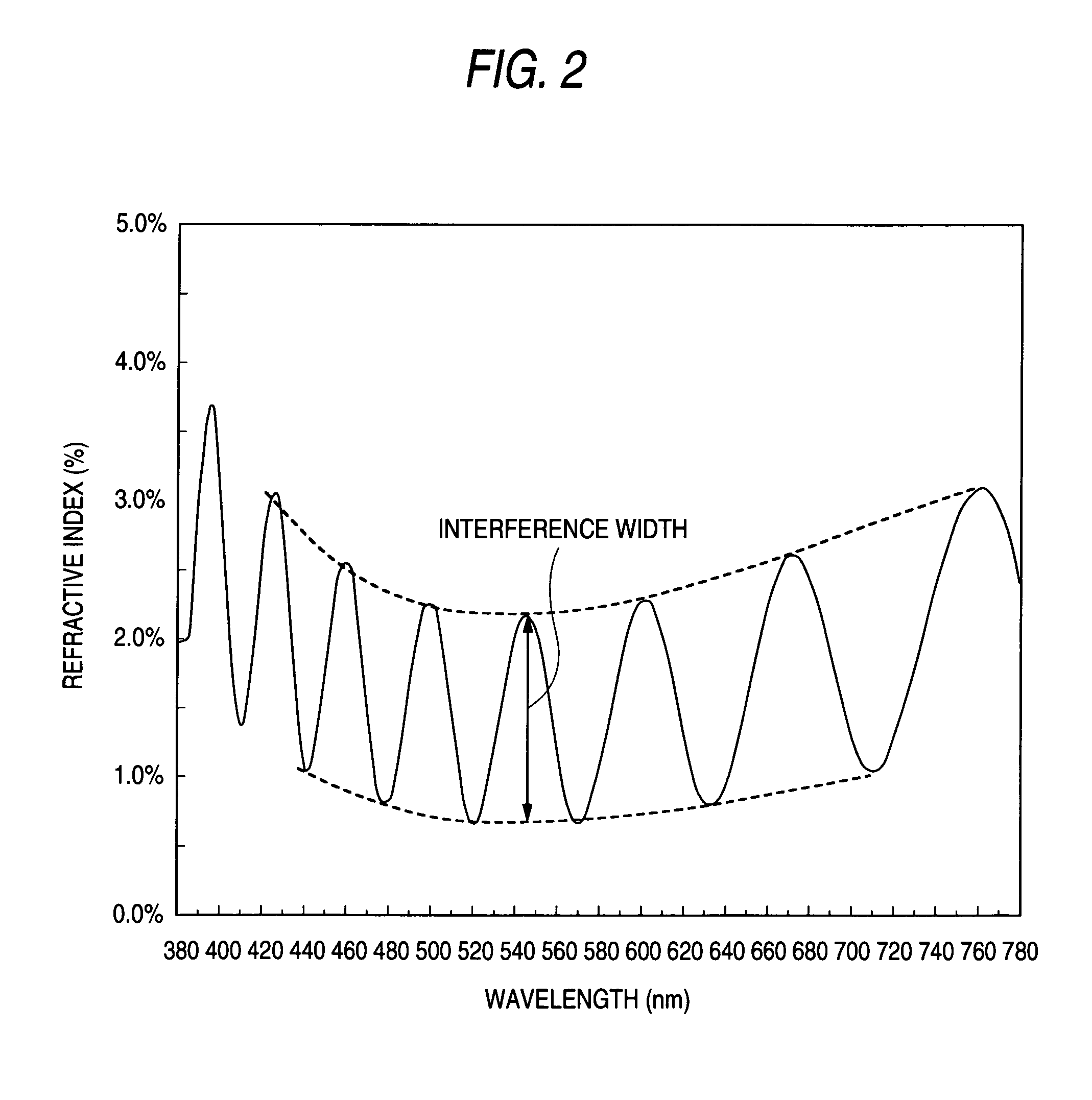
In such antireflection films having a high refractive index layer and a low refractive index layer stacked one after another, interference unevenness tends to appear owing to a difference in a refractive index between the high refractive index layer and support.
This interference unevenness leads to a quality-wise problem, because it is visualized as an irregular color of the film.

Method used


Image

  • Antireflection film, and image display device
  • Antireflection film, and image display device
  • Antireflection film, and image display device

Examples


example 1

(Preparation of Matting Agent Particle Dispersions A to L)

[0187]To 80 parts by mass of methyl ethyl ketone were added 20 parts by mass of matting agent particles as shown in Table 1, followed by dispersion in a Polytron homogenizer or sand grinder, whereby dispersions A to L as shown in Table 1 were prepared. The volume-equivalent average particle size and particle size distribution S of the resulting dispersions were measured by “Multisizer” of Malvern Instruments. These results are shown in Table 1.

[0188]

TABLE 1(Details of the dispersion of matting agent particles)RefractiveAverageParticleindex ofparticlesizeKind of particlesparticlessize (μm)distribution SDispersion ASX-50H (crosslinked polystyrene)1.610.50.8Dispersion BSX-130H (crosslinked1.611.31.0polystyrene)Dispersion CSX-200H (crosslinked1.612.00.5polystyrene)Dispersion DSX-350H (crosslinked1.613.50.8polystyrene)Dispersion ESX-500H (crosslinked1.615.00.8polystyrene)Dispersion FSGP-100C (crosslinked1.61251.3polystyrene)Disper...

example 2

[0234]In a similar manner to preparation of the coating solution B for a high refractive index layer in Example 1 except that the matting agent particle dispersions H to L shown in Table 1 were added to give the amount of the matting agent particles (the number of the matting agent particles protruding from the high refractive index layer) on the surface as shown in Table 4, followed by filtration through a polypropylene filter having a pore size of 30 μm, whereby coating solutions for a high refractive index layer were prepared.

[0235]In a similar manner to Example 1 except for the use of the resulting coating solutions instead, samples of an antireflection film shown in Table 4 were formed. Although the amount of the matting agent was fixed in Samples 2-B to 2-G and 2-J to 2-M, the number of matting agent particles protruding from the surface decreases with an increase in the film thickness of the high refractive index layer in Samples 2-B to 2-G exhibiting S=1.5, thus having a wid...


PUM

PropertyMeasurementUnit
Lengthaaaaaaaaaa
Lengthaaaaaaaaaa
Lengthaaaaaaaaaa

Abstract

Provided is an antireflection film comprising a transparent support, at least one high refractive index layer having a refractive index higher by 0.05 or greater but not greater than 1.5 than that of the transparent support and a low refractive index layer having a refractive index lower by 0.05 or greater but not greater than 2.0 than that of the high refractive index layer, wherein the high refractive index layer contains matting agent particles having an average particle size of 0.3 μm or greater but not greater than 20 μm; and the film has a haze value of 10% or less. This antireflection film has a low reflectance, is clear, has a surface less tinged with white and has reduced color due to interference, so that it is suitably used for image display devices such cathode ray tube display device (CRT), plasma display panel (PDP) and liquid crystal display (LCD). The film is also used for a polarizing plate.

Description

TECHNICAL FIELD[0001]The present invention relates to an antireflection film which is clear, has a surface not so tinged with white and is improved to have less interference unevenness; and an image display device using the film.BACKGROUND ART[0002]In image display devices such as cathode ray tube display device (CRT), plasma display panel (PDP) and liquid crystal display device (LCD), in order to prevent a deterioration in the contrast or reflection by the display due to reflection of external light, antireflection films are usually disposed on the outermost surface of the display as a film for reducing a reflectance based on the principle of optical interference.[0003]As a method of forming antireflection films, generally known is a method of applying an optically functional layer to a transparent support. For the purpose of antireflection, a reflectance can be reduced, for example, by disposing a layer (low refractive index layer) having a lower refractive index than that of the ...

Claims


Application Information

Patent Timeline
IPC IPC(8): G02B1/10B32B5/16B32B7/02B32B27/18C03C17/00C03C17/34C03C17/42G02B5/20
CPCB32B27/18C03C17/007C03C17/34C03C17/42C03C2217/475C03C2217/734G02B1/111H01J2329/892Y10T428/24355Y10T428/26Y10T428/25
Inventor IKEYAMA, AKIHIRO
Owner FUJIFILM CORP
Learn More