Coin discrimination apparatus and method

a coin discrimination and apparatus technology, applied in the field of coin discrimination apparatus and method, can solve the problems of insatiable environment for undesirably large proportion of discrimination errors, and inability to operate coin handlers and sensors that might be operable for a one-at-a-time coin environment, etc., and achieves high degree of automation, high tolerance, and convenient use

Inactive Publication Date: 2007-05-08
COINSTAR LLC
View PDF203 Cites 74 Cited by
  • Summary
  • Abstract
  • Description
  • Claims
  • Application Information

AI Technical Summary

Benefits of technology

[0013]The present invention provides a device for processing and / or discriminating coins or other objects, such as discriminating among a plurality of coins or other objects received all at once, in a mass or pile, from the user, with the coins or objects being of many different sizes, types or denominations. The device has a high degree of automation and high tolerance for foreign objects and less-than-pristine objects (such as wet, sticky, coated, bent or misshapen coins), so that the device can be readily used by members of the general public, requiring little, if any, training or instruction and little or no human manipulation or intervention, other than inputting the mass of coins.
[0014]According to one embodiment of the invention, after input and, preferably, cleaning, coins are singulated and move past a sensor for discrimination, counting and / or sorting. In general, coin slowing or adhesion is reduced by avoiding avoiding extensive flat regions in surfaces which contact coins (such as making such surfaces curved, quilted or dimpled). Coin paths are configured to flare or widen in the direction of coin travel to avoid jamming.
[0015]A singulating coin pickup assembly is preferably provided with two or more concentrically-mounted disks, one of which includes an integrated exit ledge. Movable paddles flex to avoid creating or exacerbating jams and deflect over the coin exit ledge. Vertically stacked coins tip backwards into a recess and slide over supporting coins to facilitate singulation. At the end of a transaction, coins are forced along the coin path by a rake, and debris is removed through a trap door. Coins exiting the coin pickup assembly are tipped away from the face-support rail to minimize friction.
[0017]In one embodiment, data relating to conductance of the coin (or portions thereof) as a function of diameter are analyzed (e.g. by comparing with conductance-diameter data for known coins) in order to discriminate the sensed coins. Preferably, the detection procedure uses several thresholds or window parameters to provide high recognition accuracy.
[0018]According to one aspect of the invention, a coin discrimination apparatus and method is provided in which an oscillating electromagnetic field is generated on a single sensing core. The oscillating electromagnetic field is composed of one or more frequency components. The electromagnetic field interacts with a coin, and these interactions are monitored and used to classify the coin according to its physical properties. All frequency components of the magnetic field are phase-locked to a common reference frequency. The phase relationships between the various frequencies are locked in order to avoid interference between frequencies and with any neighboring cores or sensors and to facilitate accurate determination of the interaction of each frequency component with the coin.

Problems solved by technology

Previous coin handling devices, and sensors therein, however, have suffered from a number of deficiencies.
Many previous sensors have result in an undesirably large proportion of discrimination errors.
At least in some cases this is believed to arise from an undesirably small signal to noise ratio in the sensor output.
Coin handlers and sensors that might be operable for a one-at-a-time coin environment may not be satisfactory for an environment in which a mass or plurality of coins can be received in a single location, all at once (such as a tray for receiving a mass of coins, poured into the tray from, e.g., a coin jar).
Such sensors and circuitry were not able to provide information specific to certain regions or levels of the coin (such as core material vs. cladding material).
In some currencies, two or more denominations may have average characteristics which are so similar that it is difficult to distinguish the coins.
For example, it is difficult to distinguish U.S. dimes from pre-1982 U.S. pennies, based only on average differences, the main physical difference being the difference in cladding (or absence thereof).
In embodiments in which only a single parameter is used, discrimination among coins and other small objects was often inaccurate, yielding both misidentification of a coin denomination (false positives), and failure to recognize a coin denomination (false negatives).
Multiplying the number of sensors in a device increases the cost of fabricating, designing, maintaining and repairing such apparatus.
This spacing increases the physical size requirements for such a device, and may lead to an apparatus which is relatively slow since the path which the coins are required to traverse is longer.
Furthermore, when two or more sensors each output a single parameter, it is typically difficult or impossible to base discrimination on the relationship or profile of one parameter to a second parameter for a given coin, because of the difficulty in knowing which point in a first parameter profile corresponds to which point in a second parameter profile.
If there are multiple sensors spaced along the coin path, the software for coin discrimination becomes more complicated, since it is necessary to keep track of when a coin passes by the various sensors.
It is believed that, in general, providing two or more different measurement locations or times, in order to measure two or more parameters, or in order to use two or more frequencies, leads to undesirable loss of coin throughput, occupies undesirably extended space and requires relatively complicated circuits and / or algorithms (e.g. to match up sensor outputs as a particular coin moves to different measurement locations).
With many previous sensors, the interaction of generated magnetic flux with the coin was too low to permit the desired efficiency and accuracy of coin discrimination, and resulted in an insufficient signal-to-noise ratio.
Many previous coin handling devices and sensors had characteristics which were undesirable, especially when the devices were for use by untrained users.
Such previous devices had insufficient accuracy, short service life, had an undesirably high potential for causing user injuries, were difficult to use, requiring training or extensive instruction, failed, too often, to return unprocessed coins to the user, took too long to process coins, had an undesirably low throughput, were susceptible to frequent jamming, which could not be cleared without human intervention, often requiring intervention by trained personnel, could handle only a narrow range of coin types, or denominations, were overly sensitive to wet or sticky coins or foreign or non-coin objects, either malfunctioning or placing the foreign objects in the coin bins, rejected an undesirably high portion of good coins, required frequent and / or complicated set-up, calibration or maintenance, required too large a volume or footprint, were overly-sensitive to temperature variations, were undesirably loud, were hard to upgrade or retrofit to benefit from new technologies or ideas, and / or were difficult or expensive to design and manufacture

Method used


Image

  • Coin discrimination apparatus and method
  • Coin discrimination apparatus and method
  • Coin discrimination apparatus and method

Examples


Embodiment Construction

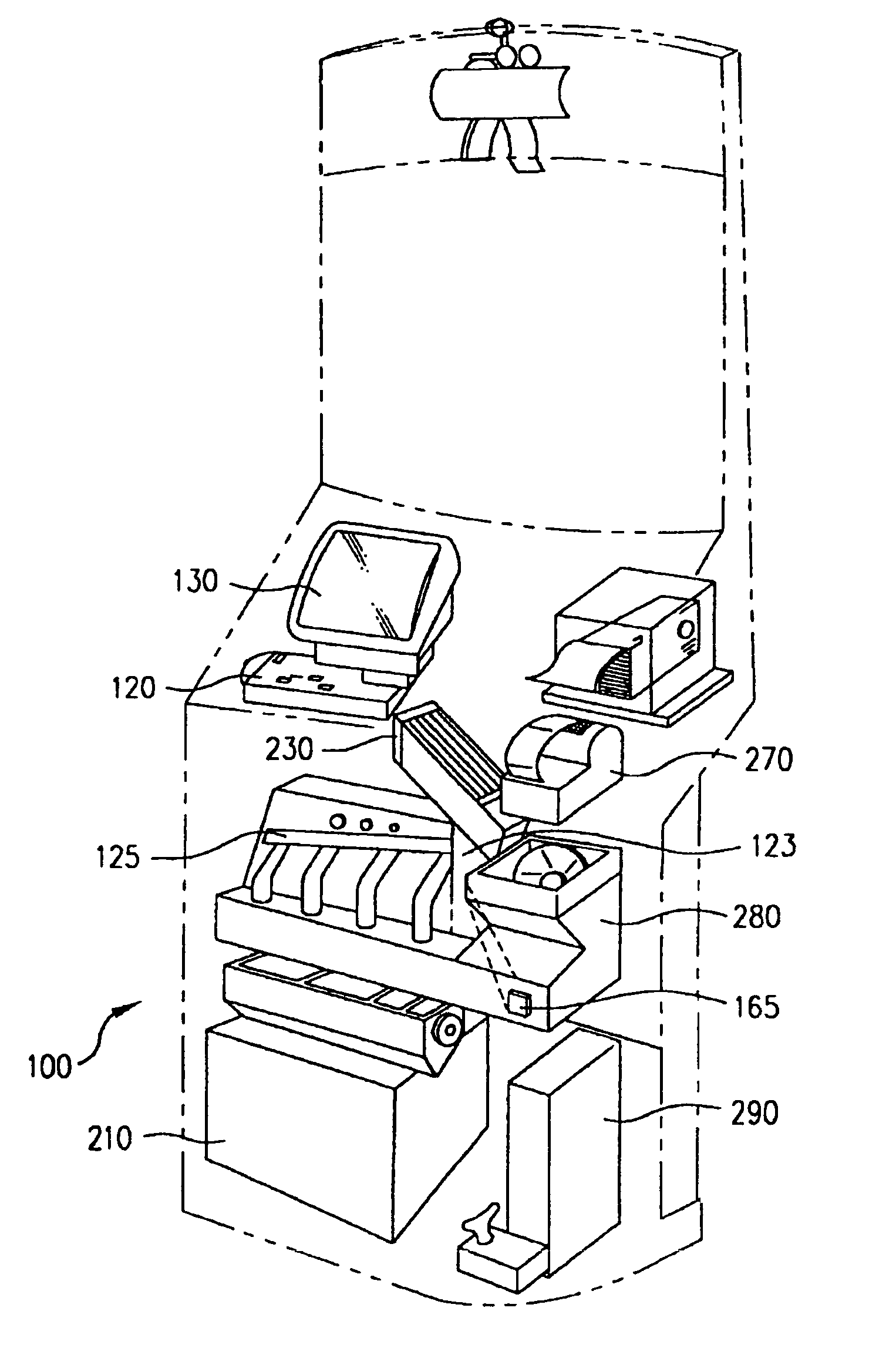
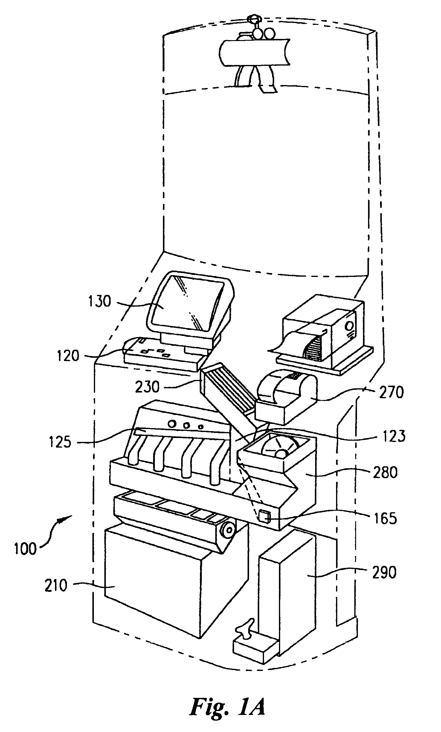
[0086]The sensor and associated apparatus described herein can be used in connection with a number of devices and purposes. One device is illustrated in FIG. 1A In this device, coins are placed into a tray 120, and fed to a sensor region 123 via a first ramp 230 and coin pickup assembly 280. In the sensor region 123, data is collected by which coins are discriminated from non-coin objects, and different denominations or countries of coins are discriminated. The data collected in the sensor area 123 is used by the computer at 290 to control movement of coins along a second ramp 125 in such a way as to route the coins into one of a plurality of bins 210. The computer may output information such as the total value of the coins placed into the tray, via a printer 270, screen 130, or the like. In the depicted embodiment, the conveyance apparatus 230, 280 which is upstream of the sensor region 123 provides the coins to the sensor area 123 serially, one at a time.

[0087]The embodiment depic...


PUM


Abstract

A coin discrimination apparatus and method is provided. Coins, preferably after cleaning, e.g. using a trommel, are singulated by a coin pickup assembly configured to reduce jamming. A coin rail assists in providing separation between coins as they travel past a sensor. The sensor provides an oscillating electromagnetic field generated on a single sensing core. The oscillating electromagnetic field is composed of one or more frequency components. The electromagnetic field interacts with a coin, and these interactions are monitored and used to classify the coin according to its physical properties. All frequency components of the magnetic field are phase-locked to a common reference frequency. The phase relationships between the various frequencies are fixed, and the interaction of each frequency component with the coin can be accurately determined without the need for complicated electrical filters. In one embodiment, a sensor having a core, preferably ferrite, which is curved, such as in a U-shape or in the shape of a section of a torus, and defining a gap, is provided with a wire winding for excitation and / or detection. The sensor can be used for simultaneously obtaining data relating to two or more parameters of a coin or other object, such as size and conductivity of the object. Two or more frequencies can be used to sense core and / or cladding properties. Objects recognized as acceptable coins, using the sensor data, are diverted by a controllable deflecting door, to tubes for delivery to acceptable coin bins.

Description

[0001]The present application is a continuation of U.S. application Ser. No. 10 / 336,617 filed Jan. 2, 2003 now U.S. Pat. No. 6,766,892, which is a continuation of U.S. application Ser. No. 09 / 703,946 filed Oct. 31, 2000 now U.S. Pat. No. 6,520,308, which is a continuation of U.S. application Ser. No. 09 / 105,403 filed Jun. 26, 1998 (now U.S. Pat. No. 6,196,371), which is a continuation-in-part of U.S. application Ser. No. 08 / 883,780 filed Jun. 27, 1997 (now U.S. Pat. No. 5,988,348), which is a continuation-in-part of U.S. application Ser. No. 08 / 807,046 filed Feb. 24, 1997, now abandoned, which is a continuation of U.S. application Ser. No. 08 / 672,639 filed Jun. 28, 1996, now abandoned: all are incorporated herein in their entireties by reference.[0002]The present invention relates to an apparatus and method for sensing coins and other small discrete objects, and in particular to an apparatus which may be used in coin counting or handling.BACKGROUND INFORMATION[0003]A number of devic...

Claims


Application Information

Patent Timeline
Patent Type & Authority Patents(United States)
IPC IPC(8): G07D5/08G07D3/06G07D3/12G07D3/14G07D5/00G07D9/00G07F5/24
CPCG07D3/06G07D3/123G07D3/14G07D3/16G07D5/00G07D5/02G07D5/08G07D9/008G07F5/24Y10S193/01
Inventor MARTIN, DOUGLAS ALANWAECHTER, MARK LOUISBERHO, RODRIGOPARTLOW, JOHN
Owner COINSTAR LLC
Why Eureka
Try Eureka