Signal processing device and signal processing method

a signal processing and signal processing technology, applied in the direction of digital signal error detection/correction, recording signal processing, instruments, etc., can solve the problems of data not being properly reproduced, binarization cannot be properly performed, and asymmetric waveform distortion generation in the amplitude direction, so as to reduce the reproduction error rate and accurately detect the effect of errors

Inactive Publication Date: 2007-05-08
COLLABO INNOVATIONS INC
View PDF10 Cites 18 Cited by
  • Summary
  • Abstract
  • Description
  • Claims
  • Application Information

AI Technical Summary

Benefits of technology

[0015]The present invention has been devised for the purpose of solving the above-described problems. It is therefore an object of the present invention to provide a signal processing device and a signal processing method in which by controlling a gain and an offset without depending on asymmetry of a reproduction signal, the location of the center of an eye diagram can be offset-controlled so that the center location is normalized in the amplitude direction and upper and lower envelopes of the reproduction signal are gradually approaching to predetermined levels, respectively, and by detecting the offset-controlled center location of the eye diagram, the asymmetry amount can be accurately detected without depending on an input reproduction signal.
[0016]To achieve the above-described object, according to the present invention, in a signal processing device for reproducing recorded information on a information recording medium, a feedback loop structure including an operational amplifier unit for amplifying a reproduction signal of the recorded information and a gain / offset control unit for controlling a gain and an offset of the operational amplifier unit so that each of the amplitude and the offset of an output of the operational amplifier unit becomes a predetermined value is adopted, DC component information of the reproduction signal is extracted from signals of the feedback loop and the DC component information is supplied as information indicating the asymmetry amount of the reproduction signal. With this structure, the signal amplitude and the offset can be controlled so that the reproduction signal is effectively within a predetermined level range and a DC component information with which a duty ratio after binarization substantially becomes a predetermined value can be obtained. Thus, the location of the center of the reproduction signal eye pattern can be detected, so that the asymmetry amount can be accurately measured.
[0017]If using information for the asymmetry amount detected in the above-described manner, change of a judgment level of a Viterbi decoder, ON / OFF control of Viterbi decoding, equalizer property control or offset operation of a binarization circuit is performed, the reproduction error rate can be reduced.

Problems solved by technology

In the PWM recording method, when a recording mark is formed to be large or small depending on recording conditions, the duty ratio of a reproduction signal shifts from a predetermined value, resulting in the generation of asymmetric waveform distortion in the amplitude direction.
However, as shown in FIG. 3, when aliasing distortion of a reproduction waveform is generated and a large asymmetry is present, a binarization level overlaps aliasing part of the waveform and binarization can not be properly performed with the configuration of FIG. 2.
As a result, data is not properly reproduced.
However, the PRML technique is designed based on an ideal waveform exhibiting vertical symmetry in the amplitude direction, and when strong asymmetry occurs in a reproduction signal and the vertical symmetry in the amplitude direction is largely lost, the Viterbi decoder 109 does not properly operate.
However, in general, the amplitude of a reproduction signal from a pickup for reading recorded information is very small.
Therefore, it is necessary to acquire a large gain so that a desired signal amplitude is achieved in an amplifier in a subsequent stage, but amplification by DC coupling is difficult because of a constraint of a dynamic range of the subsequent stage amplifier.
Thus, the asymmetry amount information can not be obtained from each of the slice levels itself.

Method used


Image

  • Signal processing device and signal processing method
  • Signal processing device and signal processing method
  • Signal processing device and signal processing method

Examples


Embodiment Construction

[0036]Hereinafter, embodiments of the present invention relating to a signal processing device for reproducing a recorded information on information recording medium will be described in detail with reference to the accompanying drawings.

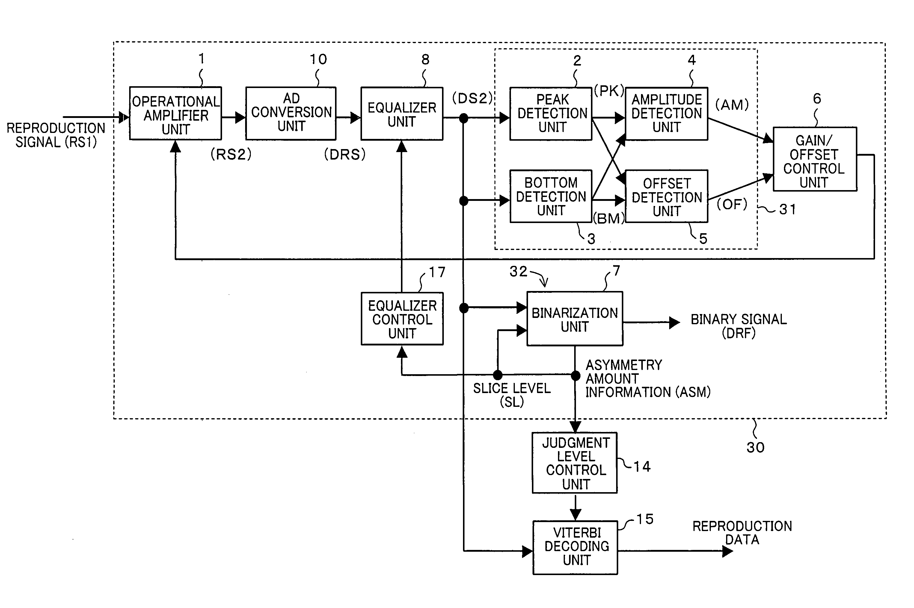
[0037]FIG. 6 is a block diagram of an asymmetry detector in a signal processing device according to the present invention. An asymmetry detector 30 of FIG. 6 includes an operational amplifier unit 1 for receiving a reproduction signal (RS1) of a recorded information on a recording medium as an input and giving a gain corresponding to a gain control signal input and a DC offset corresponding to an offset control signal input, an equalizer unit 8 for emphasizing a high frequency band of an output (RS2) of the operational amplifier unit 1, a peak detection unit 2 for receiving an output (RS3) of the equalizer unit 8 as an input and performing peak detection, a bottom detection unit 3 for receiving the output (RS3) of the equalizer unit 8 as an input an...


PUM

PropertyMeasurementUnit
currentaaaaaaaaaa
cutoff frequencyaaaaaaaaaa
frequencyaaaaaaaaaa

Abstract

A feedback loop structure including an operational amplifier unit (1) for amplifying a reproduction signal of recorded information and a gain / offset control unit (6) for controlling an amplitude and an offset of an output of the operational amplifier unit (1) so that each of the amplitude and the offset becomes a predetermined value is adopted, and accurate information for an asymmetry amount is obtained by a binarization unit (7) for receiving the output of the operational amplifier unit (1) and performing binarization while adjusting a slice level by feedback control so that a duty ratio after the binarization substantially becomes a predetermined value. Based on the asymmetry amount information, a judgment level of a Viterbi decoding unit (15) is changed, thereby reducing a reproduction error rate.

Description

TECHNICAL FIELD[0001]The present invention relates to a technique for accurately detecting an asymmetry amount of a reproduction signal generated due to change in recording conditions and the like and, furthermore, reducing an error rate using information for the asymmetry amount in a signal processing device for reproducing data from recorded information on an information recording medium.BACKGROUND ART[0002]In recent years, a rapid development of increasing the density of optical disks has been made and, with this rapid development, recording of a moving picture image with a large capacity has become possible. Moreover, optical disks as a storage medium have excellent properties such as excellent capacitive properties and high speed accessibility, can be provided at low cost, and also is interchangeable. In view of these points, it is highly possible that optical disks will take place tape recording medium.[0003]As for recording methods for optical disks, there are the PPM (pulse ...

Claims


Application Information

Patent Timeline
Patent Type & Authority Patents(United States)
IPC IPC(8): G11B7/00G11B20/10
CPCG11B20/10009G11B2020/1863G11B7/005G11B20/10G11B20/14G11B20/18
Inventor HORIBE, RYUSUKEAIDA, KAZUTOSHI
Owner COLLABO INNOVATIONS INC
Why Eureka
Try Eureka