Distortion compensation circuit

a distortion compensation and circuit technology, applied in the direction of amplifier modification to reduce non-linear distortion, digital transmission, baseband system details, etc., can solve the problems of large power consumption, large scale and high price, and difficult to improve the efficiency of an amplification system using the feedforward method, so as to improve the stability of distortion compensation

Inactive Publication Date: 2007-05-08
NEC CORP
View PDF12 Cites 15 Cited by
  • Summary
  • Abstract
  • Description
  • Claims
  • Application Information

AI Technical Summary

Benefits of technology

[0026]An object of the present invention is to provide a distortion compensation circuit capable of reducing a convergence time before a completion of convergence of distortion compensation data without impairing any stability of distortion compensation.
[0028]According to the present invention, in the error computation and compensation data updating section, step coefficients by which an amplitude error and a phase error computed by comparing the demodulated feedback orthogonal baseband signal and the input orthogonal baseband transmission signal on a polar coordinate system are multiplied are changed according to the amplitude value of the orthogonal baseband transmission signal. Updating of compensation data up to a component of a large input signal amplitude with which only a small number of error data samples are obtained can therefore be performed in a shorter time. The time before the completion of convergence of distortion compensation can be reduced to a large extent and the stability of distortion compensation can be improved.
[0036]According to the present invention, the step coefficient changed according to the amplitude value of the orthogonal baseband transmission signal is changed to a smaller step coefficient to further improve the stability of distortion compensation after convergence of distortion compensation data.

Problems solved by technology

A power amplifier having good linearity with respect to a wide amplitude component range, however, is large in scale and high-priced and has large power consumption.
It is difficult to improve the efficiency of an amplification system using the feedforward method because of the need for an error amplifier.
In the Cartesian feedback method, however, the amount of improvement in distortion is proportional to the loop gain and it is, therefore, difficult to increase the bandwidth in which a distortion improvement effect can be achieved in increasing the distortion improvement effect and maintaining the loop stability in feedback.
Consequently, it is not possible to achieve a reduction in convergence time while improving the stability of distortion compensation with respect to all amplitude values.
As described above, the conventional distortion compensation circuit has a problem in that, since the step coefficients in repeated computation for obtaining distortion compensation data are set to constant values regardless of the amplitude value of input signals, it is not possible to reduce the convergence time while maintaining the stability of distortion compensation.

Method used


Image

  • Distortion compensation circuit
  • Distortion compensation circuit
  • Distortion compensation circuit

Examples


second embodiment

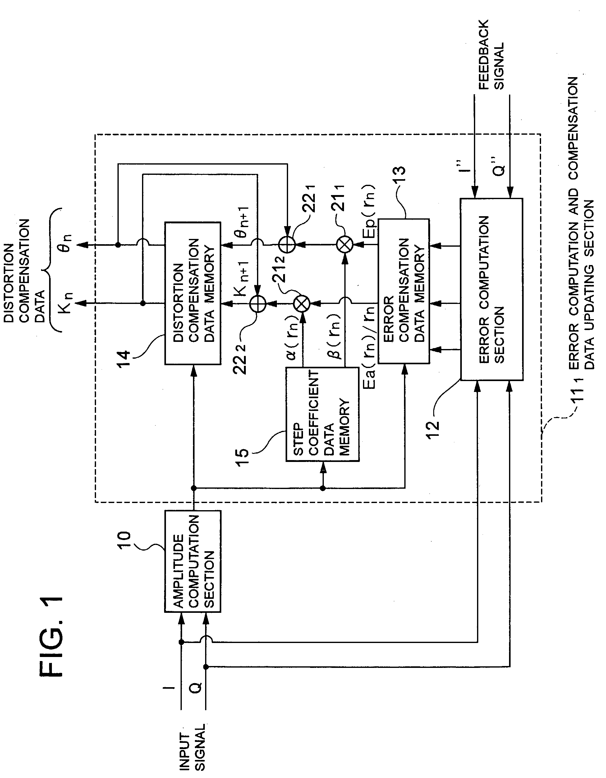
[0062]The error computation and compensation data updating section 112 in the distortion compensation circuit according to the present invention differs from the error computation and compensation data updating section 111 shown in FIG. 1 in that the former has a step coefficient computation section 16 in place of the step coefficient data memory 15.

[0063]The step coefficient computation section 16 computes step coefficients α(rn) and β(rn) corresponding to the amplitude value rn computed by the amplitude computation section 10 by using an approximation equation having the input signal amplitude value rn as a variable, and outputs the computed step coefficients α(rn) and β(rn) to the multipliers 211 and 212.

[0064]In the distortion compensation circuit according to the first embodiment, step coefficients α(rn) and β(rn) corresponding to the input signal amplitude value rn are read out from the step coefficient data memory 15 to be used for computation of amplitude compensation data K...

third embodiment

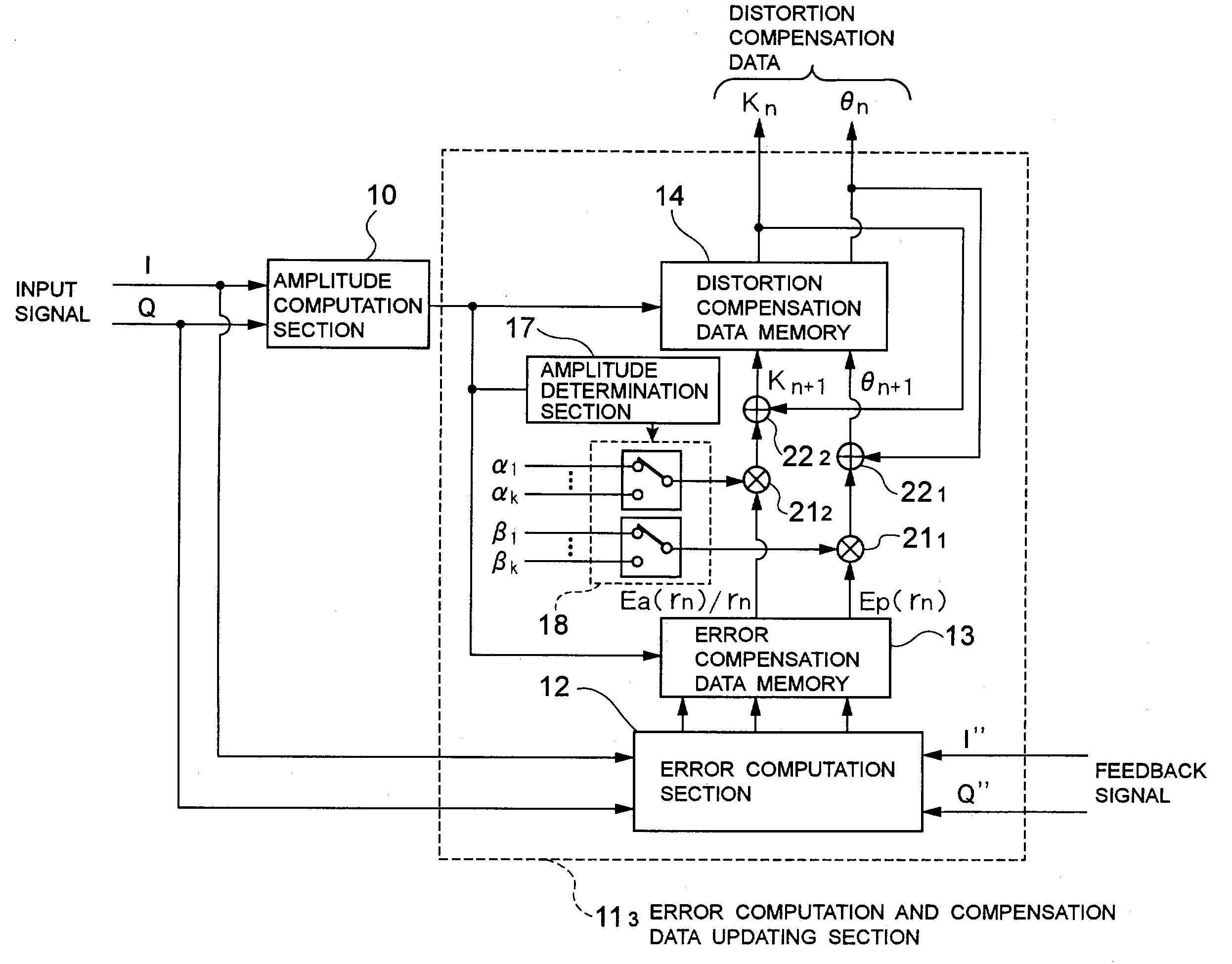
[0066]The error computation and compensation data updating section 113 in the distortion compensation circuit according to the present invention differs from the error computation and compensation data updating section 111 shown in FIG. 1 in that the former has an amplitude determination section 17 and a selector 18 in place of the step coefficient data memory 15.

[0067]The amplitude determination section 17 compares the input signal amplitude value rn computed by the amplitude computation section 10 with at least one amplitude threshold value set in advance. The selector 18 selects, on the basis of the result of comparison in the amplitude determination section 17, one of amplitude compensation data step coefficients (α1, α2, . . . , αk) and one of phase compensation data step coefficients (β1, β2, . . . , βk), and outputs the selected step coefficients to the multipliers 211 and 212.

[0068]The step coefficients are set so that α12k, and β12k. In these inequalities, k is an integer e...

fourth embodiment

[0072]A distortion compensation circuit according to the present invention will be described.

[0073]The distortion compensation circuit according to the fourth embodiment of the present invention is arranged in such a manner that the error computation and compensation data updating section 91 in the conventional distortion compensation circuit shown in FIG. 9 is replaced with an error computation and compensation data updating section shown in FIG. 6.

[0074]The error computation and compensation data updating section in the distortion compensation circuit according to the fourth embodiment of the present invention is arranged in such a manner that, as shown in FIG. 6, a selector change determination section 19 and a selector 20 are added to the error computation and compensation data updating section 111 shown in FIG. 1. In FIG. 6, components identical or corresponding to those shown in FIG. 1 are indicated by the same reference characters.

[0075]The selector 20 performs switching betw...


PUM


Abstract

Disclosed is a distortion compensation circuit that reduces the time for convergence of distortion compensation data, without impairing any stability of distortion compensation. The circuit includes an error computation and compensation data updating section that repeats a computation in which errors between an input orthogonal baseband transmission signal and a feedback signal obtained by demodulating part of the output from a power amplifier are computed to obtain error data and values obtained by multiplying this error data by step coefficients are added to distortion compensation data before updating, thereby computing distortion compensation data after updating. Distortion compensation data for compensation of nonlinear distortion is thus updated. Step coefficients are stored in a step coefficient data memory with respect to each of different input signal amplitude values. Step coefficients corresponding to an input signal amplitude value computed by an amplitude computation section are output from the memory to multipliers.

Description

BACKGROUND OF THE INVENTION[0001]1. Field of the Invention[0002]The present invention relates to a distortion compensation circuit which is used in a wireless transmitting apparatus such as a base station in a wireless communication system to make compensation for a distortion caused in amplification means such as a power amplifier which amplifies an input signal.[0003]2. Description of the Related Art[0004]In a wireless transmitting apparatus in a wireless communication system, it is ideal to use a power amplifier having linearity with respect to all amplitude components in order to minimize adjacent-channel-leakage power as small as possible. A power amplifier having good linearity with respect to a wide amplitude component range, however, is large in scale and high-priced and has large power consumption. In some case, therefore, there is no way other than a power amplifier having nonlinearity with respect to large-amplitude components while having good linearity with respect to s...

Claims


Application Information

Patent Timeline
Patent Type & Authority Patents(United States)
IPC IPC(8): H04K1/02H04L25/03H04L25/49H03F1/32
CPCH03F1/3247
Inventor DOI, YOSHIAKI
Owner NEC CORP
Why Eureka
Try Eureka