Structure of transformer

a transformer and structure technology, applied in the direction of transformer/inductance details, inductance, electrical equipment, etc., can solve the problems of affecting the resonant circuit of the power supply system, the structure of the transformer is readily distorted, and the procedure of wrapping the tape , so as to achieve effective control and increase the leakage inductance, the effect of enhancing the electric safety

Inactive Publication Date: 2007-05-15
DELTA ELECTRONICS INC
View PDF4 Cites 26 Cited by
  • Summary
  • Abstract
  • Description
  • Claims
  • Application Information

AI Technical Summary

Benefits of technology

[0010]It is an object of the present invention to provide a structure of a transformer for effectively controlling and increasing leakage inductance, and enhancing electric safety.

Problems solved by technology

Since the tape 24 is made of flexible material and fails to be firmly fixed, the structure of the transformer is readily distorted due to a long-term using period or serious vibration.
Under this circumstance, the magnitude of the leakage inductance is reduced or unstable, and the resonant circuit of the power supply system will be adversely affected.
Since these tapes are sticky and narrow in width, the procedures of wrapping the tape 24, the first side tape 25 and the second side tape 26 are labor-intensive and complicated.
In addition, if the wrapping result is unsatisfied, the electrical performance of the transformer is impaired.
The insulating tape also impairs heat dissipation of the transformer during operation.
Furthermore, since the secondary winding coil of the conventional transformer is manually wound and fabricated, the labor cost is increased and the fabricating efficiency is reduced.
The diameter of the secondary winding coil is too small to be used in high power application.

Method used


Image

  • Structure of transformer
  • Structure of transformer
  • Structure of transformer

Examples


Embodiment Construction

[0028]The present invention will now be described more specifically with reference to the following embodiments. It is to be noted that the following descriptions of preferred embodiments of this invention are presented herein for purpose of illustration and description only. It is not intended to be exhaustive or to be limited to the precise form disclosed.

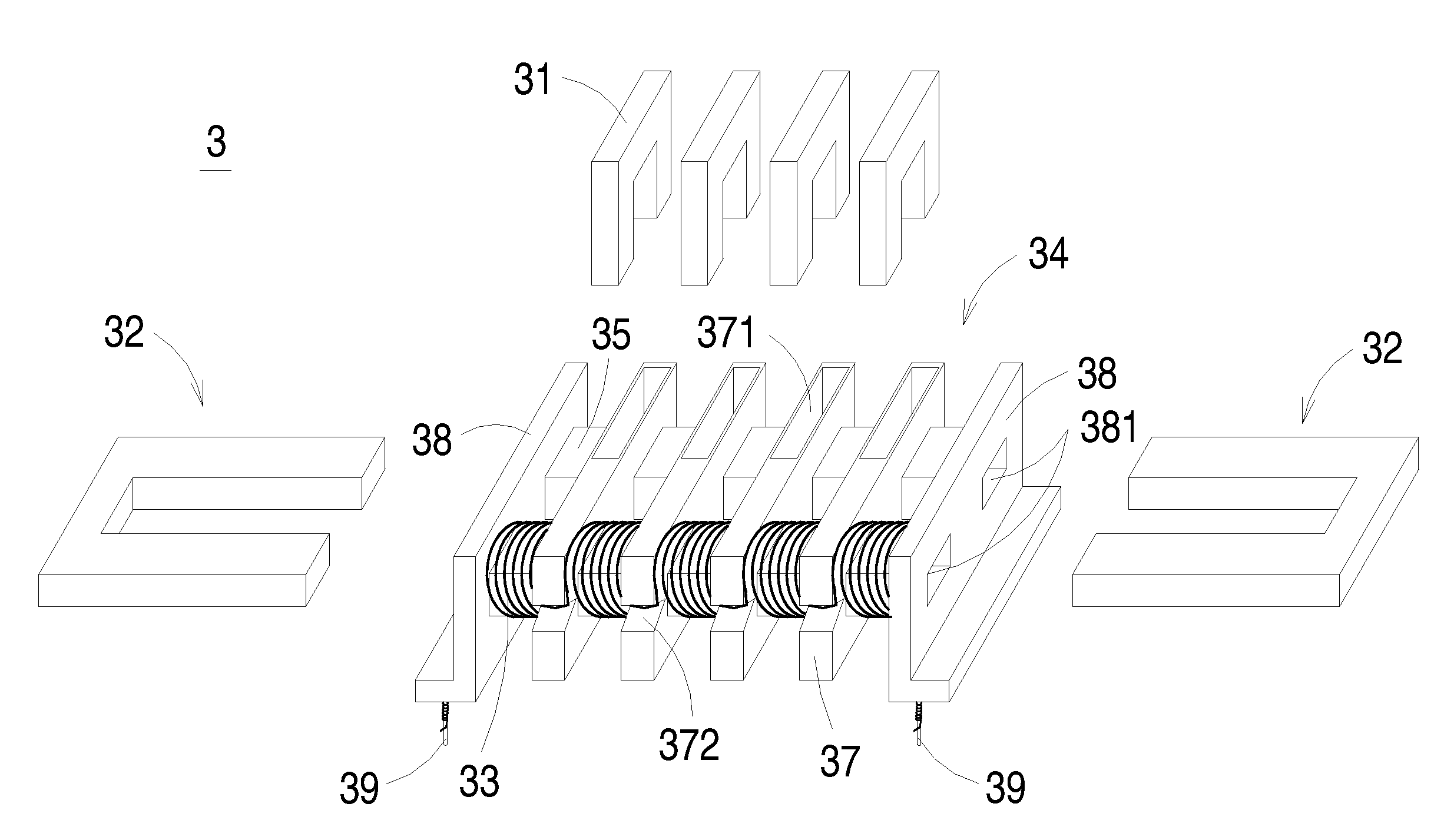
[0029]Referring to FIGS. 3(a) and 3(c), schematic exploded views of a transformer according to a first preferred embodiment of the present invention is illustrated. The transformer 3 comprises a plurality of electrically-conductive sheets 31, a magnetic core assembly 32, a primary winding coil 33 (as shown in FIG. 3(c)) and a bobbin 34.

[0030]The bobbin 34 comprises a first tube member 35, a second tube member 36, plural partition plates 37, two side plates 38 and plural pins 39. The first tube member 35 and the second tube member 36 are arranged between and connected to these two side plates 38. The first tube member 35 and the s...


PUM

PropertyMeasurementUnit
electrically-conductiveaaaaaaaaaa
magneticaaaaaaaaaa
leakage inductanceaaaaaaaaaa

Abstract

A transformer includes a primary winding coil, a plurality of electrically-conductive sheets, a bobbin and a magnetic core assembly. The bobbin includes a first tube member, a second tube member and plural partition plates. The first tube member and the second tube member have a first channel and a second channel therein, respectively. Each partition plate is sheathed around the first tube member and the second tube member and includes a receptacle for accommodating respective electrically-conductive sheet, and the primary winding coil is wound around the second tube member.

Description

FIELD OF THE INVENTION[0001]The present invention relates to a structure of a transformer, and more particularly to a structure of a transformer having increased leakage inductance.BACKGROUND OF THE INVENTION[0002]A transformer has become an essential electronic component for various kinds of electric appliance. Referring to FIG. 1, a schematic exploded view of a conventional transformer is illustrated. The transformer 1 principally comprises a magnetic core assembly 11, a bobbin 12, a primary winding coil 13 and a secondary winding coil 14. The primary winding coil 13 and the secondary winding coil 14 are wounded around the bobbin 12. A tape 15 is provided for isolation and insulation. The middle portions 111 of the core 11 are embedded into the cylinder tube 121 of the bobbin 12. The primary winding coil 13 and the secondary winding coil 14 interact with the magnetic core assembly 11 to achieve the purpose of voltage regulation.[0003]Since the leakage inductance of the transformer...

Claims


Application Information

Patent Timeline
Patent Type & Authority Patents(United States)
IPC IPC(8): H01F27/24
CPCH01F27/2866H01F38/08H01F27/266H01F27/306
Inventor CHANG, SHIH-HSIEN
Owner DELTA ELECTRONICS INC
Why Eureka
Try Eureka