
Integrated planar composite coupling structures for bi-directional light beam transformation between a small mode size waveguide and a large mode size waveguide

a composite coupling and light beam technology, applied in the field of optical structures, can solve the problems of reducing alignment sensitivity and small optical structure, and achieve the effect of reducing fabrication cos

Inactive Publication Date: 2007-05-15
HO SENG TIONG
View PDF14 Cites 83 Cited by
  • Summary
  • Abstract
  • Description
  • Claims
  • Application Information

AI Technical Summary

Benefits of technology

[0045]The integrated composite coupling structures of the present invention provide an integrated approach to optical mode transformation. The integrated approach allows fabrication of a large number of couplers using established processes used frequently in electronics industries and photonic integrated circuit industries, thereby resulting in lower fabrication cost. The composite optical structures allow the beam to be transformed differently in the vertical and lateral directions.
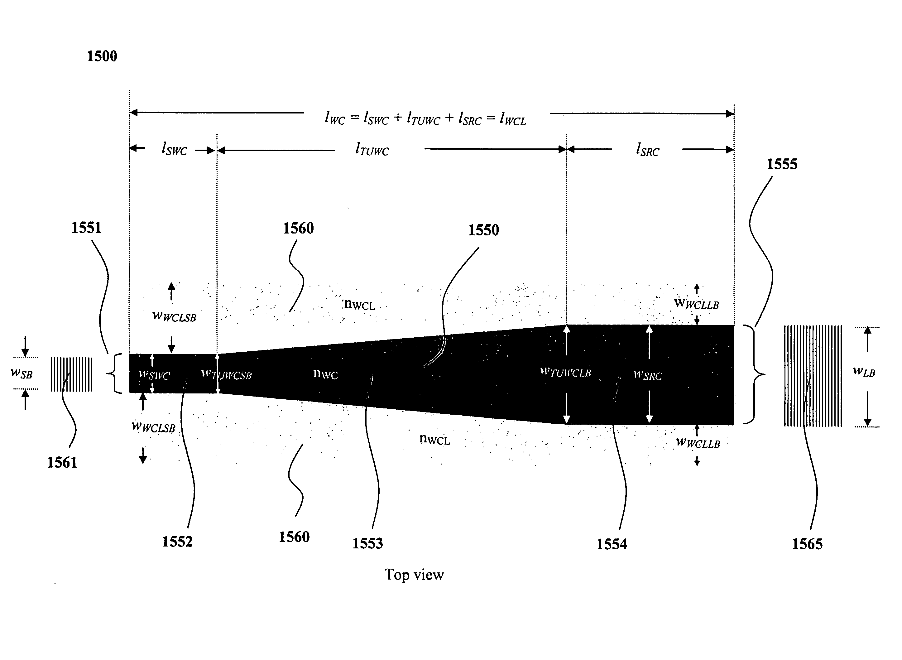
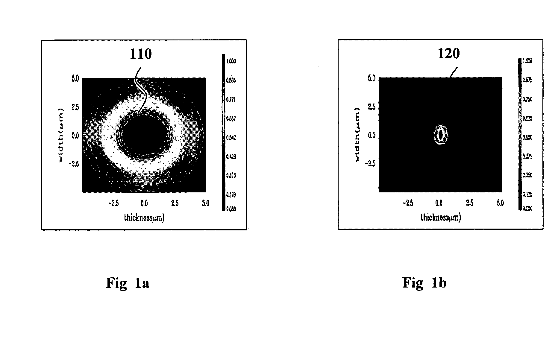
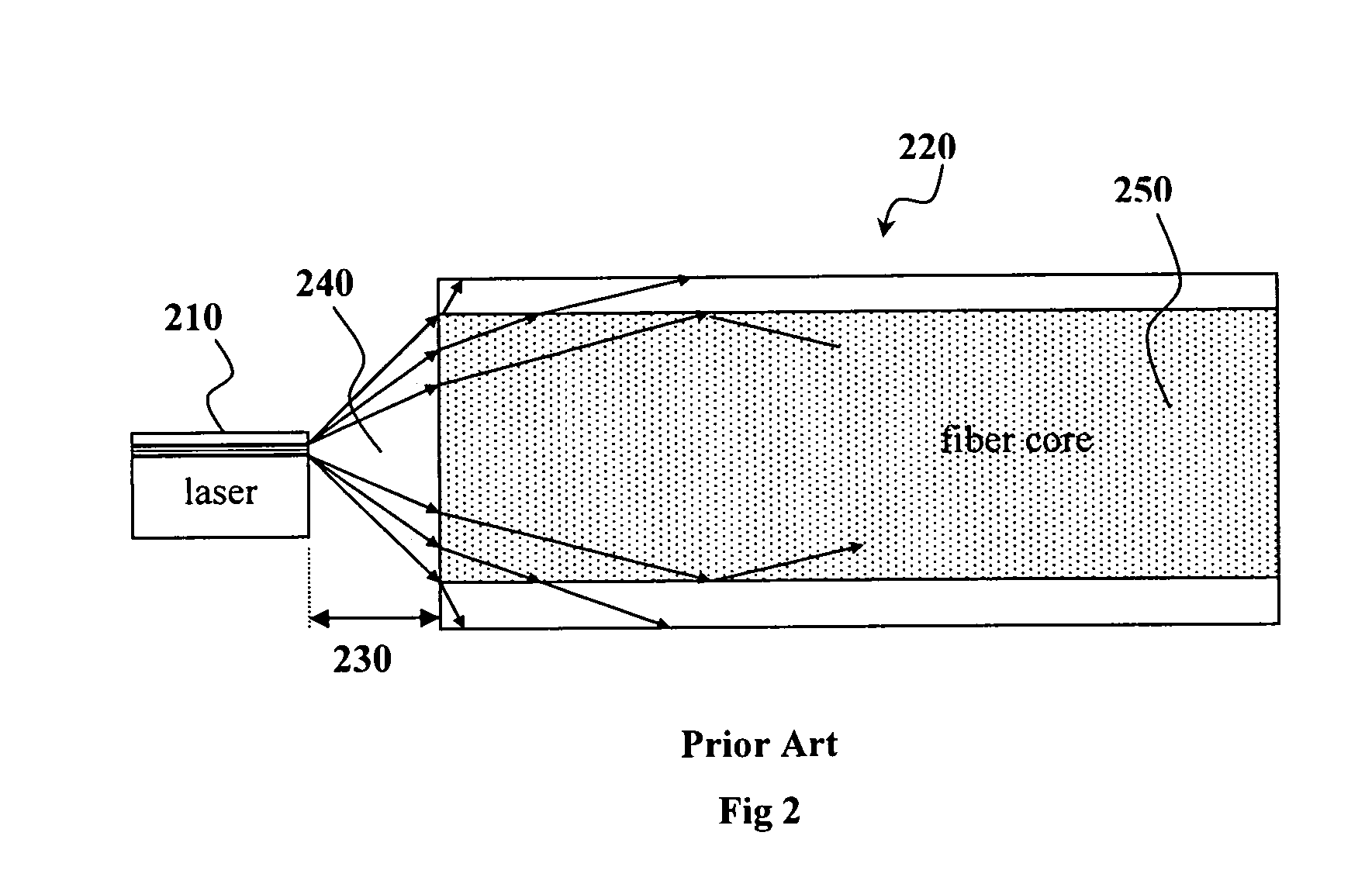
[0046]An embodiment of the present invention provides a planar optical structure that can transform the vertical mode size between a photonic device and an optical fiber. The size of the optical structure is small relative to the optical fiber diameter, which reduces alignment sensitivity. In one aspect of the present invention, the vertical mode transformation is achieved via the use of a micro vertical graded refractive index (μ-VGRIN) structure that is capable of beam size transformation down to below λ / 1.5 (or 1 μm for λ=1.5 μm). Moreover, the μ-VGRIN structure can be fabricated according to the present invention using established process technology such as Jon-Assisted-Deposition with low cost and low optical loss.
[0049]In yet another aspect of the present invention, μ-VGRIN structure is combined with a micro-lateral graded refractive index (μ-LGRIN) structure to achieve separate transformation of the vertical and lateral beam sizes. The μ-LGRIN structure can be fabricated with low cost and large quantity using UV-imprinting process used in the photonic industry. The composite μ-VGRIN and μ-LGRIN structure can include a cascaded or concurrent geometry.
[0050]In yet another aspect of the present invention, a high-refractive-index-contrast vertical sharp taper (HRC-VST) and dielectric structure is used for which the relative refractive index of the vertical taper material is substantially higher than that of the dielectric material. The high index contrast allows beam transformation down to about λ / 15 (or 0.1 μm for λ=1.5 μm) when the taper is made up of silicon and the dielectric is made up of glass. The HRC-VST can be fabricated according to the present invention using established processes in the electronics and photonics industries with low costs.
[0053]In yet another aspect of the present invention, the sharp taper is in the lateral / horizontal direction, resulting in a high-refractive-index-contrast lateral sharp taper (HRC-LST) which provide beam transformation in the lateral / horizontal direction.

Problems solved by technology

The size of the optical structure is small relative to the optical fiber diameter, which reduces alignment sensitivity.

Method used


Image

  • Integrated planar composite coupling structures for bi-directional light beam transformation between a small mode size waveguide and a large mode size waveguide
  • Integrated planar composite coupling structures for bi-directional light beam transformation between a small mode size waveguide and a large mode size waveguide
  • Integrated planar composite coupling structures for bi-directional light beam transformation between a small mode size waveguide and a large mode size waveguide

Examples


Embodiment Construction

[0108]Contents of Detailed Description

[0109]I. General Background and Terminology

[0110]II. General Introduction

[0111]III. Exemplary devices and embodiments

[0112](1) Exemplary device 1: a high-refractive-index-contrast vertical sharp-down-taper (HRC-VSDT) ICMT device

[0113](2) Exemplary device 2: a high-refractive-index-contrast lateral sharp-down-taper (HRC-LSDT) ICMT device

[0114](3) Exemplary device 3: a high-refractive-index-contrast-lateral gradual-up-taper (HRC-LGUT) ICMT device

[0115](4) Exemplary device 4: a vertical sharp-down-taper and lateral gradual-up-taper (VSDT×LGUT) ICMT device

[0116](5) Exemplary device 5: a lateral-step-refractive-index and vertical-step-refractive-index (LSRIN×VSRIN) ICMT device

[0117](6) Exemplary device 6:

[0118](A) a composite-lateral-step-refractive-index and vertical-graded-refractive index (LSRIN×VGRIN) ICMT device

[0119](B) a composite-lateral-graded-refractive-index and vertical-graded-refractive index (LGRIN×VGRIN) ICMT device

[0120](7) Exemplary ...


PUM


Abstract

Composite optical waveguide structures or mode transformers and their methods of fabrication and integration are disclosed, wherein the structures or mode transformers are capable of bi-directional light beam transformation between a small mode size waveguide and a large mode size waveguide. One aspect of the present invention is directed to an optical mode transformer comprising a waveguide core having a high refractive index contrast between the waveguide core and the cladding, the optical mode transformer being configured such that the waveguide core has a taper wherein a thickness of the waveguide core tapers down to a critical thickness value, the critical thickness value being defined as a thickness value below which a significant portion of the energy of a light beam penetrates into the cladding layers surrounding the taper structure thereby enlarging the small mode size. This primary tapered core structure may be present in either a vertical or horizontal direction and may be combined with further up taper or down taper structures in the directions transverse to the primary taper direction. Another aspect of the present invention is directed to a non-cylindrical graduated refractive index (GRID) lens structure. The non-cylindrical GRIN structure has a graded refractive index having a maximum value at its core and a minimum value at its outer edges. The grading of the refractive index is provided in a either the vertical or horizontal directions and may have either a fixed refractive index or a graded refractive index in the transverse directions. Yet another aspect of the present invention is directed to composite optical mode transformers that are combinations of the taper waveguide structures and the non-cylindrical graduated refractive index structures. Yet another aspect of the present invention is the further integration of the mode transformers with V-grooves for multiple input / output fibers and alignment platform for multiple input / output photonic chips or devices.

Description

CROSS REFERENCES TO RELATED APPLICATIONS[0001]This application is a continuation of U.S. patent application Ser. No. 10 / 083,674, filed Oct. 19, 2001 now abandoned, and this application also claims the benefit of U.S. Provisional Application 60 / 242,213, filed Oct. 20, 2000, entitled, MULTIPORT INTEGRATED COUPLER FOR BI-DIRECTIONAL LIGHT BEAM TRANSFORMATION BETWEEN A SMALL SIZE WAVEGUIDE AND A LARGE SIZE WAVEGUIDE, the entire contents of which applications are hereby incorporated by reference in their entirety as if set forth in full in this document.BACKGROUND OF THE INVENTION[0002]1. Field of the Invention[0003]The present invention relates, in general, to optical structures that enable optical beam transformation between a large-mode-size waveguide and a small-mode-size waveguide, and methods of making the same. In particular, the present invention relates to methods for transforming the optical mode between a photonic device and one or more optical fibers. The present invention al...

Claims


Application Information

Patent Timeline
Patent Type & Authority Patents(United States)
IPC IPC(8): G02B6/26G02B6/42G02B6/12G02B6/122G02B6/14
CPCG02B6/1228G02B6/14G02B6/4206G02B2006/12176G02B2006/12188
Inventor ZHOU, YANHO, SENG-TIONG
Owner HO SENG TIONG
Learn More