Biochemical assay detection in a liquid receptacle using a fiber optic exciter

a fiber optic exciter and liquid receptacle technology, applied in the field of biochemical assays performed in rec, can solve the problems of loss of assay sensitivity, loss of much of excitation light, and limited sensitivity of pierced mirror systems, and achieve maximum signal-to-noise ratio, no loss of intensity, and enhanced use

Inactive Publication Date: 2007-05-15
BIO RAD LAB INC
View PDF25 Cites 6 Cited by
  • Summary
  • Abstract
  • Description
  • Claims
  • Application Information

AI Technical Summary

Benefits of technology

[0010]Preferred excitation light sources are those supplying ultraviolet, visible, or near-infrared light, optically coupled with the optical fiber so that substantially all of the light from the light source enters the fiber for transmission to the receptacle interior. This will result in substantially no loss of intensity between the light source and the receptacle. The optical fiber itself may be a simple fiber or one that includes such elements as a collimator or optical filter, or a collimator-filter-collimator assembly, to process the light in various ways that will enhance its use for particular applications and assays.
[0011]Systems in accordance with this invention offer numerous advantages over the prior art. By separating the excitation and emission light paths, systems in accordance with this invention limit the excitation and emission optics to a single function each, thereby permitting individual optimization of these two optical systems. In epi-illumination systems, little of the excitation light is detected in the emission light path and a maximal signal-to-noise ratio is achieved, particularly when the illumination fiber and the emission collection optics are at different angles relative to the normal axis. When the system is used on multi-well plates, only a single well is illuminated by the optical fiber and emission is collected from that well individually, thereby eliminating crosstalk and maximizing the signal of that well. This leads to maximal signal collection and superior performance for any given level of detection and sensitivity. Furthermore, excitation systems of this invention require no additional lenses or other optical elements between the excitation fiber and the assay receptacle, and can thus avoid the losses in light intensity that are often caused by these additional elements. In aspects of this invention that are directed to an optical fiber optically coupled directly to an LED or SLD light source, the coupled product is inexpensive, durable, and compact, and delivers bright light while generating minimal heat. This simplified yet highly efficient design presents advantages for packaging, cost and size reduction.

Problems solved by technology

The two frequently interfere with each other, however, resulting in a loss of assay sensitivity.
Pierced-mirror systems have limited sensitivity, however, since the need to optimize the collection of the weaker emission light requires compromises that result in loss of much of the excitation light.
As a result, these devices suffer from a reduced intensity due to restricted aperture considerations and to the misdirection of a portion of the excitation light.
The use of a dichroic mirror simplifies the optical path and instrument layout, but efficient separation of the emission light from the excitation light requires an expensive optical filter and a reduction in the signal light.

Method used


Image

  • Biochemical assay detection in a liquid receptacle using a fiber optic exciter
  • Biochemical assay detection in a liquid receptacle using a fiber optic exciter
  • Biochemical assay detection in a liquid receptacle using a fiber optic exciter

Examples


Embodiment Construction

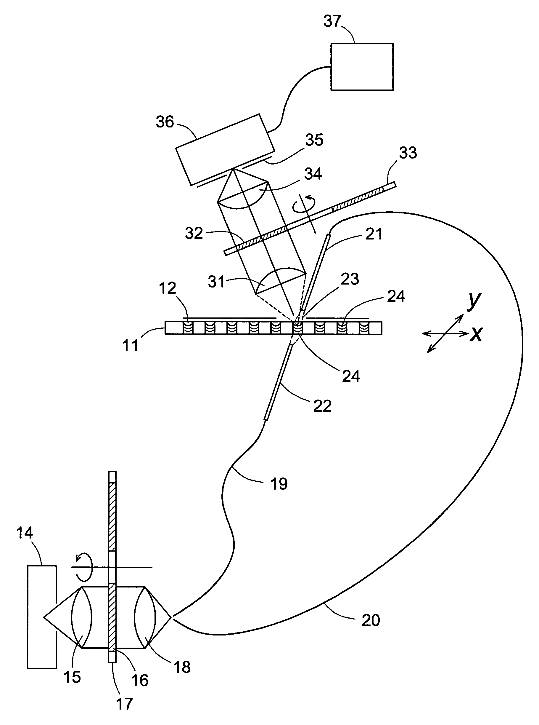
[0015]Receptacles in which bioassay detection can be performed by use of the present invention include cuvettes, small test tubes, wells of multi-well plates, and any variety of vessels capable of containing the components used in performing biochemical assays. Examples of multiwell plates are MICROTITER® plates, as well as plates bearing different designations but generally containing either a row of wells or a two-dimensional rectangular array of wells. The most commonly used multi-well plates are those with a 96-well (12×8) array. Others have 6-well, 12-well, 48-well, 384-well, and 1536-well arrays. Typical well diameters or widths are from about 4 mm to about 40 mm, and preferably from about 4 mm to about 11 mm. The emissions to be generated and detected in the practice of this invention can arise from liquid retained in the receptacle, from substances suspended in the liquid, or from substances adhering to the receptacle walls.

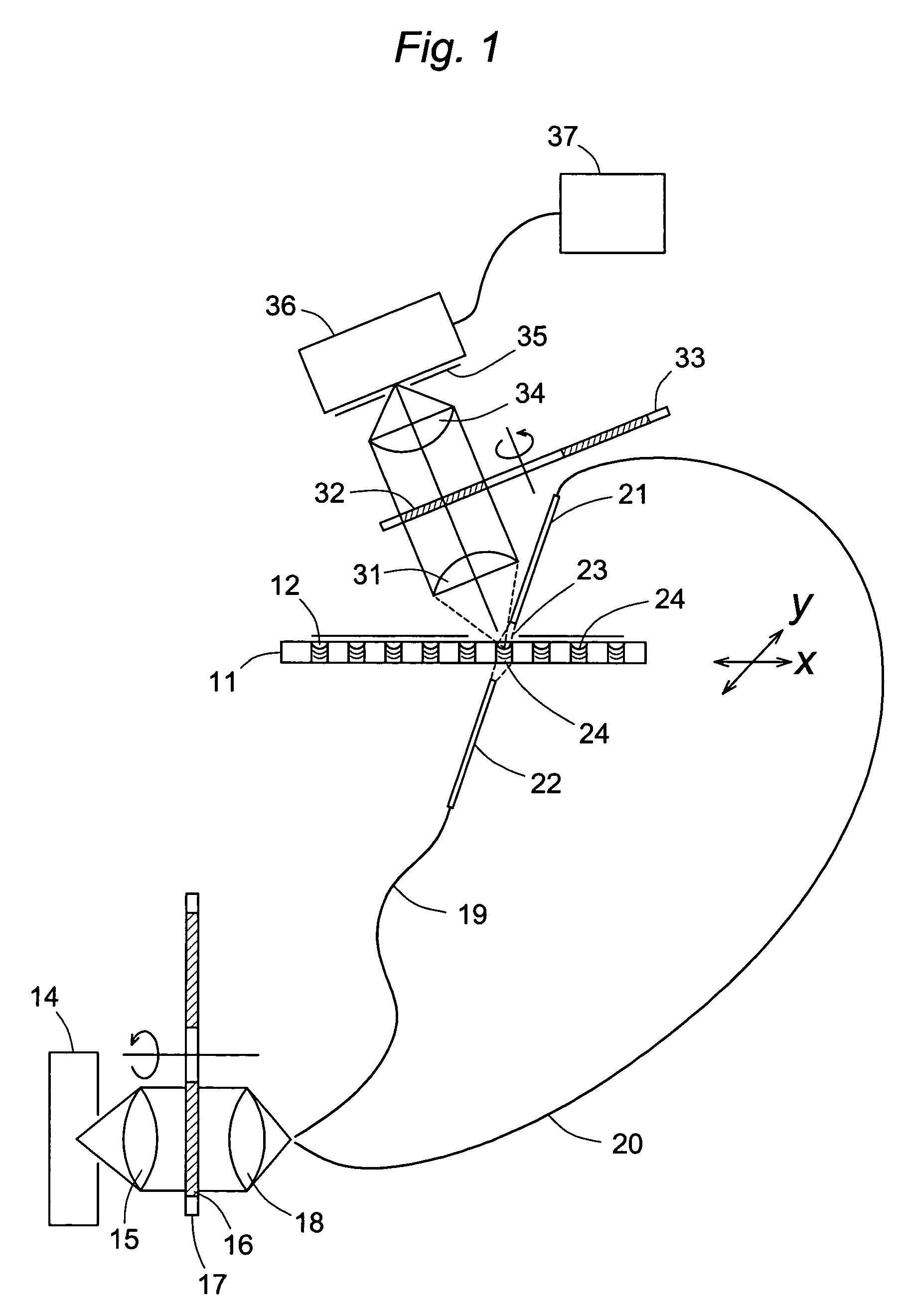
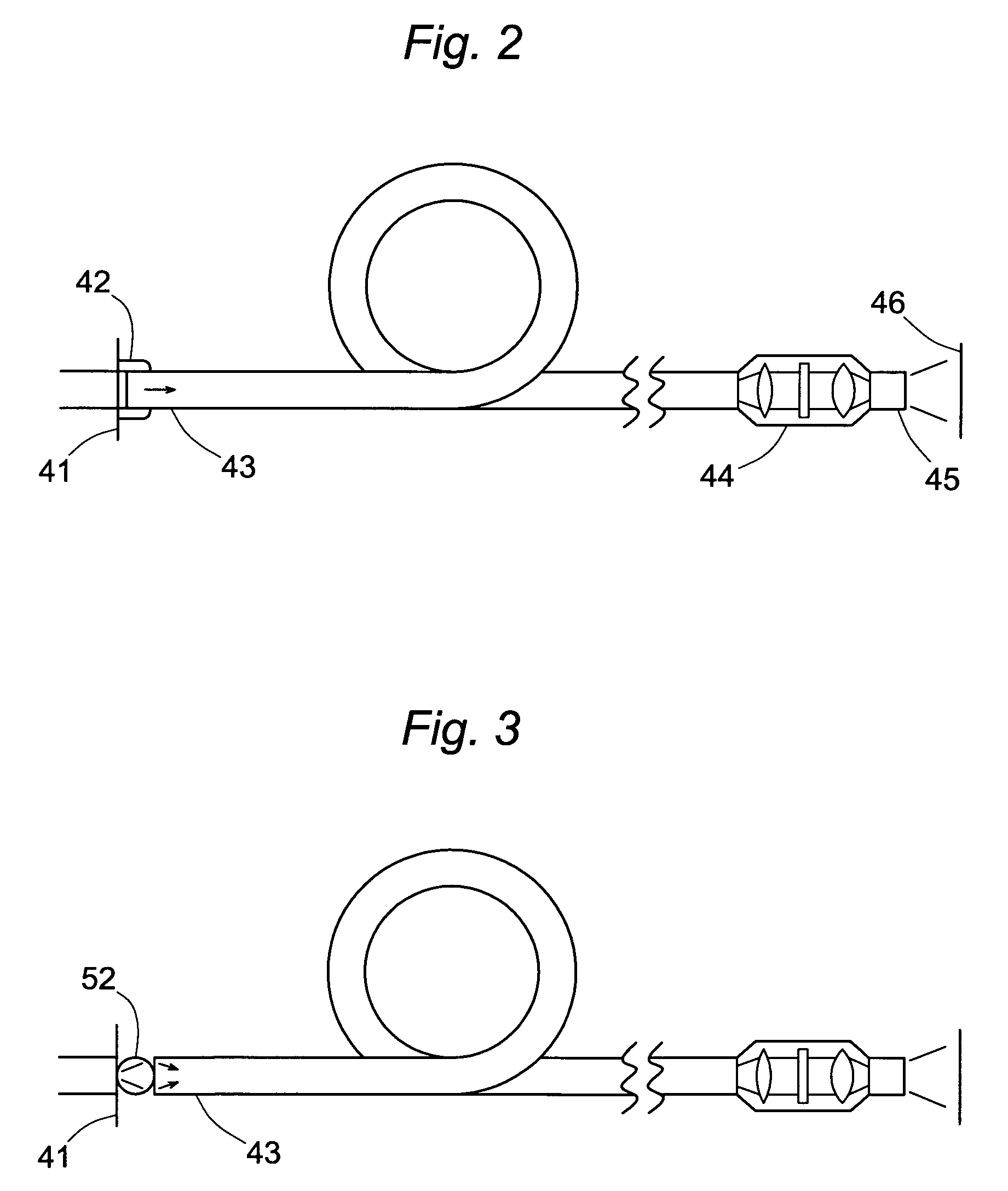
[0016]The excitation system of this invention may c...


PUM

PropertyMeasurementUnit
widthsaaaaaaaaaa
widthsaaaaaaaaaa
divergence angleaaaaaaaaaa

Abstract

Biochemical assays that are performed in cuvettes and in the wells of multi-well plates and that utilize excitation and light emission as labels for detection are enhanced by an illumination and detection system that supplies excitation light through an optical fiber that transmits excitation light from an excitation light source to the cuvette or well. Emission light produced by the excitation is then collected by a collimating lens and converted to a signal that is compiled by conventional software for analysis. The optical fiber and collimating lens can either be on the same side of the receptacle (generally the open side) or on opposite sides, i.e., one above and the other below. When the optical fiber and the collimating lens are both on the open side of the receptacle, they are arranged such that the direction of travel of the excitation light and the direction along which the emission light is collected are not coaxial, and preferably both are at an acute angle to the axis normal to the mouth of the receptacle. Illumination systems are also disclosed in which a ultraviolet, visible, or near-infrared light source is optically coupled to an optical fiber.

Description

CROSS REFERENCE TO RELATED APPLICATION[0001]This application claims the benefits of co-pending U.S. provisional patent applications Nos. 60 / 325,855 and 60 / 325,876, both filed on Sep. 27, 2001, for all purposes legally capable of being served thereby. The contents of each of these provisional patent applications are incorporated herein by reference in their entirety, as are all other patent and literature references cited throughout this specification.BACKGROUND OF THE INVENTION[0002]1. Field of the Invention[0003]This invention resides in the field of biochemical assays performed in receptacles such as cuvettes or the wells of multi-well plates such as MICROTITER® plates, and particularly in obtaining the assay results by optical excitation of the receptacle contents and detection of the emissions resulting from the excitation.[0004]2. Description of the Prior Art[0005]Fluorescence and other optical signals are widely used in biochemical assays, particularly as a label in distinguis...

Claims


Application Information

Patent Timeline
Patent Type & Authority Patents(United States)
IPC IPC(8): G02B6/32G01N1/10G02B6/00G01N21/25G01N21/64
CPCG01N21/253G01N21/6452G01N2021/6421G01N2021/6471G01N2021/6484
Inventor HILLENDAHL, JAMES W.WALDBESER, DAVID E.
Owner BIO RAD LAB INC
Why Eureka
Try Eureka