
Method and device for the detection of fault current arcing in electric circuits

a fault current and electric circuit technology, applied in the direction of electric digital data processing, emergency protection arrangements for automatic disconnection, instruments, etc., can solve the problems of arcing fire, fault current arcing, or arc tracking, which is particularly dangerous in aircraft wiring, and achieves the effect of reducing the erroneous triggering of safeguards

Active Publication Date: 2007-05-15
JENOPTIK ADVANCED SYST GMBH
View PDF9 Cites 86 Cited by
  • Summary
  • Abstract
  • Description
  • Claims
  • Application Information

AI Technical Summary

Benefits of technology

"The invention relates to a method for detecting arc faults in electric lines of consumers with relatively constant power consumption. The method involves measuring current and voltage in the load circuit and calculating the ratio of these measurements. A threshold value is set to trigger a fault signal when the ratio exceeds a predetermined threshold. The method reduces the likelihood of false triggers caused by circuit-dependent interference and ensures reliable detection of arcing. The resistance value of the load circuit is used as the ratio value, and a counter is incremented or decreased when the threshold value is exceeded. The method can be implemented using a current sensor and a voltage sensor in the load circuit, and a division element can be used to form the ratio value. The invention also includes an arrangement for detecting arc faults in a load circuit with a current sensor and a voltage sensor."

Problems solved by technology

Fault current arcing, or ‘arc tracking’, as it is called in English-language technical literature, is particularly dangerous above all in aircraft wiring for safety reasons.
The typical pattern is that insulation faults occur in the wiring of electrical consumers, particularly heating devices, due to pre-existing defects (penetration, e.g., by mechanical, chemical and / or thermal alternating loads), initiate arcing fire, and often destroy an entire area of the cable or consumer.
Often, shunts (leakage currents) with an initially high impedance occur and—usually aided by electrolytically acting liquids—lead to wet arc tracking, as it is called, subsequently decrease in impedance over the course of time and, finally, result in high-energy short-circuit arcing.
A set of problems arises in that the environment is severely compromised by a cable fire initiated in this way and explosive sequential faults can cause catastrophic air accidents.
Alternately, so-called dry arc tracking can also occur and (e.g., due to chafing of cable on sharp edges) can cause sudden low-impedance shunts (short circuits) that can lead to the same catastrophic results.
The chief problem in developing safeguards for controlling a very high-current load (e.g., an in-line heater) is that the initial currents of fault current arcs (hereinafter, for the sake of brevity, arcing) can be very small compared to the rated currents of the load in use.
On the other hand, for purposes of early detection of fault arcing, it must also be considered that the availability of aviation equipment and aviation systems is very important and, therefore, false triggering of safety measures cannot be allowed to occur.
However, no satisfactory solutions have yet been found.
This solution is disadvantageous in that the signal interpolation of the frequency response—in order to be fast—can rely on only a few current measurement values.
Also, the similarities to interference in frequent turn-on processes at the supply voltage still pose a relatively high risk of erroneous triggering of the safeguard.
Further, the signal processing is relatively elaborate, easily subject to error, and can only reasonably be applied at all for AC power supplies with a known, constant power supply frequency.
It is at least doubtful that interference caused by turn-on processes of other consumers can be safely distinguished from interference caused by arcing, so that erroneous triggering of the protective circuit cannot be ruled out.
This method is disadvantageous in that it is only suitable for AC power supply and, in addition, presupposes a relatively low power supply frequency.
The analog processing in the filter paths is complicated and relatively prone to interference signals so that erroneous triggering of the protection circuit cannot be ruled out with certainty.
This signal processing is disadvantageous in that the programming of consumer-specific “current signatures” requires the use of a processor and the large proportion of analog processing steps (integrator, bandpass filter, voltage zero crossing detection, determination of the proportion of high frequencies) increases the susceptibility of the detection circuit to interference.
High-impedance leakage current arcing is difficult to detect in this way and unnecessary erroneous triggering of the safeguard, which poses a danger vis-a-vis the safety requirements in aircraft, cannot be reliably excluded.
Moreover, most of the known solutions comprise predominantly analog evaluating circuits, which are more prone to problems.

Method used


Image

  • Method and device for the detection of fault current arcing in electric circuits
  • Method and device for the detection of fault current arcing in electric circuits
  • Method and device for the detection of fault current arcing in electric circuits

Examples


Embodiment Construction

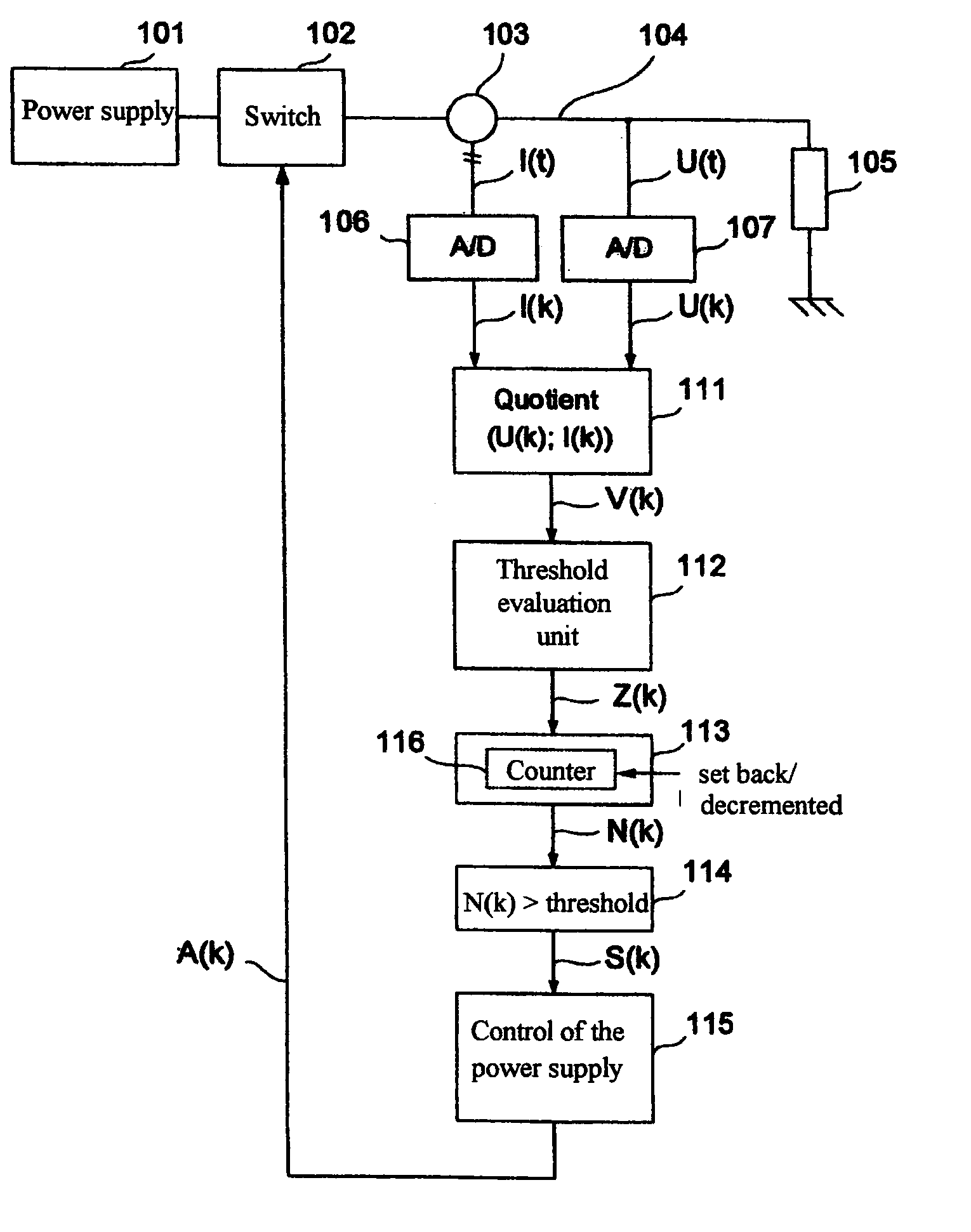
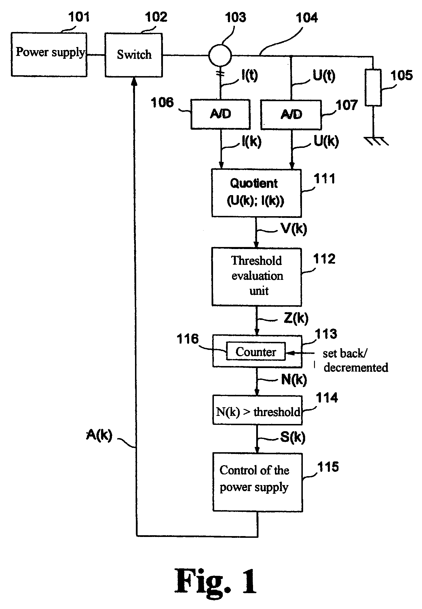
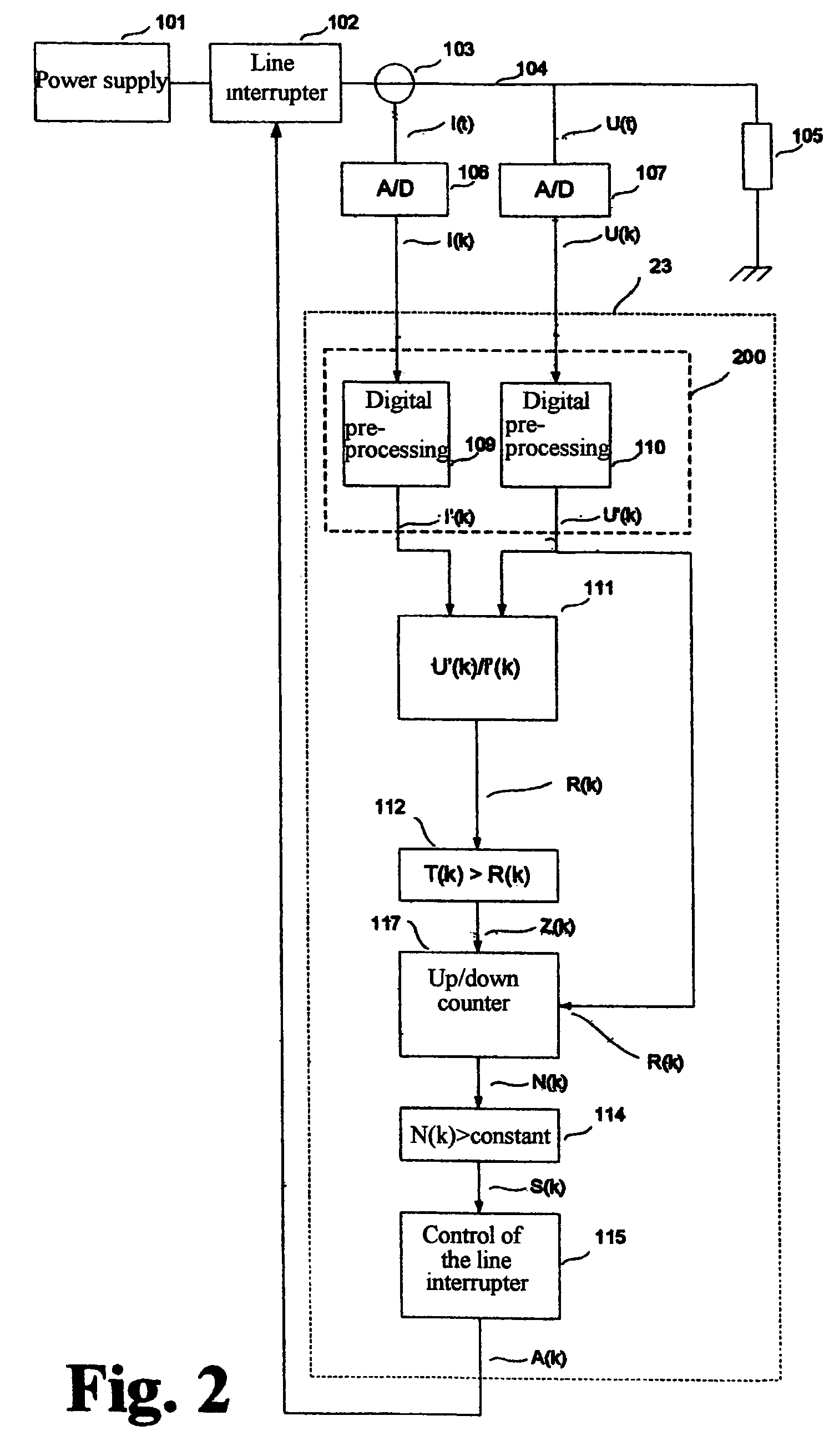
[0060]FIG. 1 shows a basic arrangement of a load circuit of any type for realizing the method according to the invention. The load circuit comprises a power supply 101, a switch 102 used for line interruption, a load 105 (e.g., a high-current heater), and an electric line 104 for supplying current to the load 105 (the current return is assumed to be a ground contact at the load 105). It is assumed that the line 104 is connected to an electric load 105 whose resistance does not change or changes only slowly.

[0061]A current sensor 103 followed by an A / D converter 106 and a voltage sensor in the form of an A / D converter 107 are arranged on the line 104 for detecting fault current arcing. Time-discrete current values I(k) and voltage values U(k) are provided synchronously at the outputs of the A / D converters 106 and 107 and are processed in a division element 111 to form an actual ratio value V(k). In so doing, either the resistance or the conductance of the load circuit can be calculat...


PUM


Abstract

The invention is directed to a method and a device for detecting fault current arcing in electric circuits for consumers with relatively constant power consumption, particularly in onboard aircraft power supplies. The object of the invention is to find a novel possibility for detecting arc faults in electric lines of consumers with a relatively constant power consumption which appreciably reduces erroneous triggering of safeguards without compromising the reliability of switching off in the event that arcing actually occurs. This object is met, according to the invention, in that a voltage value is measured simultaneous with the current measurement, a ratio is formed of the current measurement values and voltage measurement values that are detected in parallel, and an indicator signal is generated for detected arcing when changes in the ratio of current measurement values and voltage measurement values exceed a predetermined threshold value.

Description

CROSS-REFERENCE TO RELATED APPLICATIONS[0001]This application claims priority of German Application No. 10 2004 056 436.1, filed Nov. 19, 2004, the complete disclosure of which is hereby incorporated by reference.BACKGROUND OF THE INVENTION[0002]a) Field of the Invention[0003]The invention is directed to a method and a device for detecting fault current arcing in electric circuits for consumers with relatively constant power consumption, in particular for connected heating elements. The invention is applied for early detection of arcing resulting from insulation defects occurring in any voltage power supply at any power supply frequency, but particularly in onboard aircraft power supplies, due to high mechanical, chemical, electrical and / or thermal loading.[0004]b) Description of the Related Art[0005]Fault current arcing, or ‘arc tracking’, as it is called in English-language technical literature, is particularly dangerous above all in aircraft wiring for safety reasons.[0006]The ty...

Claims


Application Information

Patent Timeline
Patent Type & Authority Patents(United States)
IPC IPC(8): G06F19/00G01R31/12H02H1/00
CPCH02H1/0015G01R31/1227G01R27/16H02H3/38H02H3/40
Inventor BANKE, BORISPETERSEN, HANS-HERMANN
Owner JENOPTIK ADVANCED SYST GMBH
Learn More