

Device for milling and lathing
a technology of lathes and milling machines, applied in the direction of grinding drives, auxiliary equipment, manufacturing tools, etc., can solve the problems of limited machine height, achieve the effect of increasing the speed of workpieces, and reducing the size of workpieces
- Summary
- Abstract
- Description
- Claims
- Application Information
AI Technical Summary
Benefits of technology
Problems solved by technology
Method used
Image


Examples
Embodiment Construction
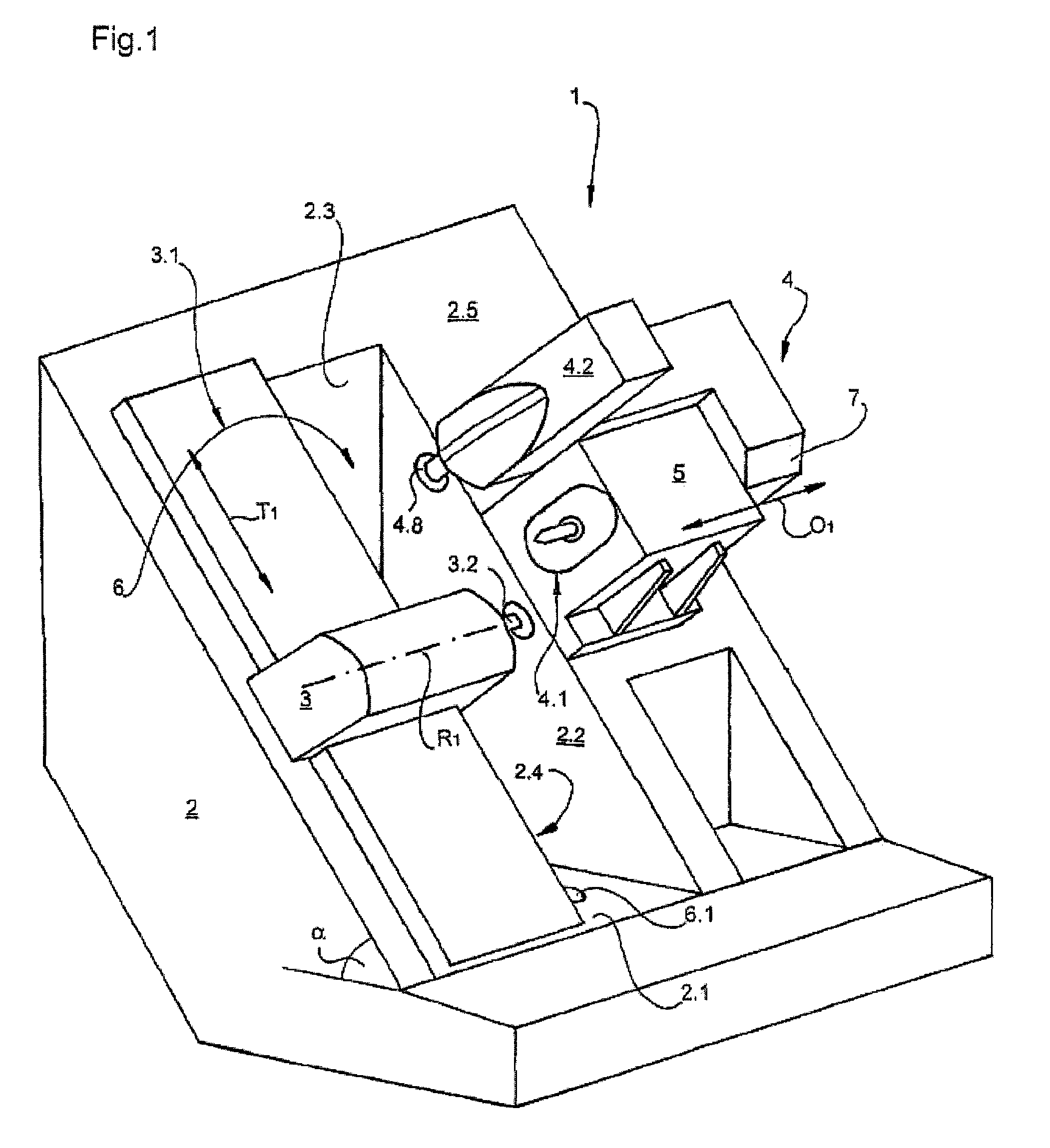
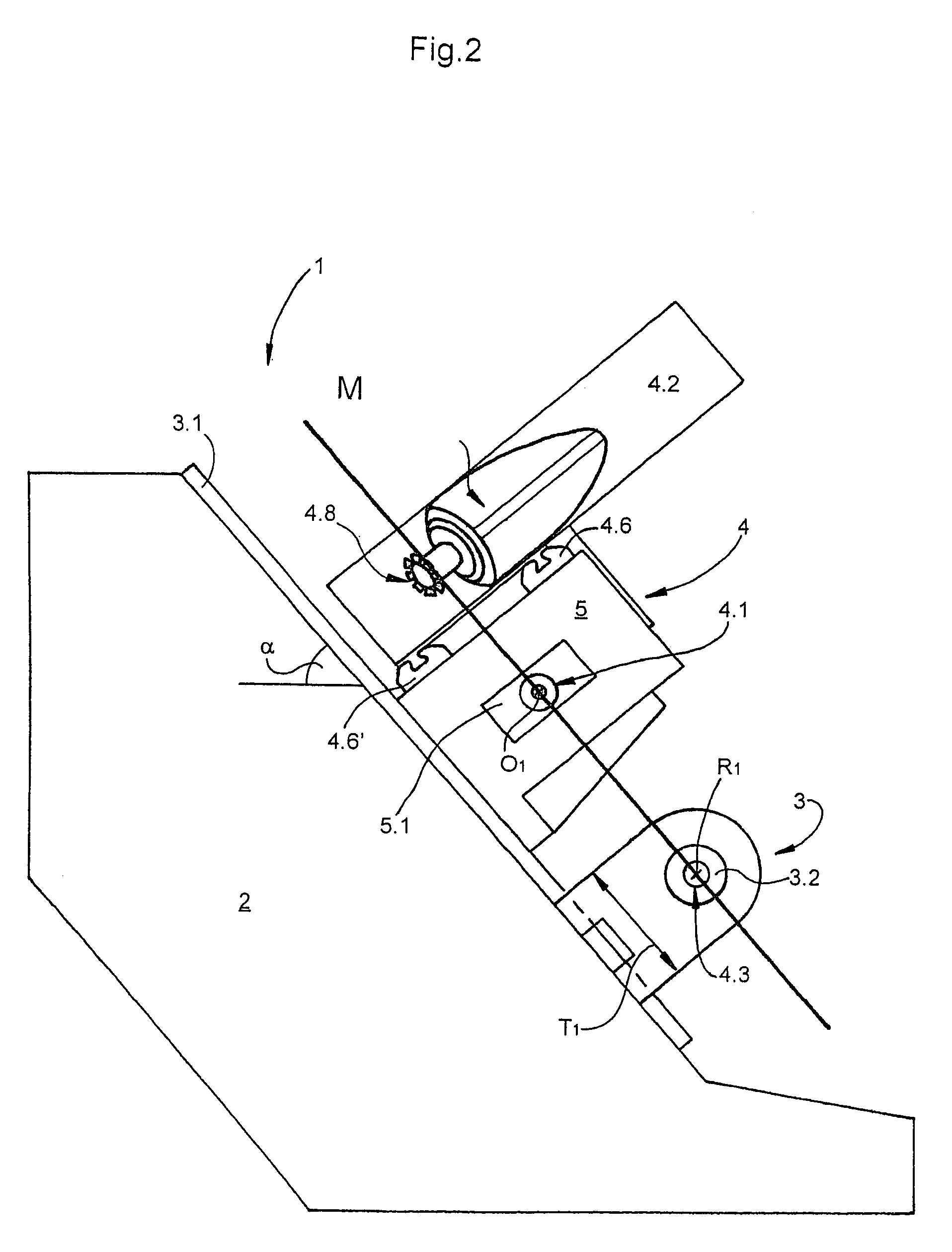
[0038]The device 1 shown in FIG. 1 has a machine bed 2 set up at an angle α relative to the horizontal. The angle α between a machine bed main surface 2.5 and the horizontal is about 50° here. The machine bed 2 also has a chip space 6 arranged approximately in the middle, which is formed by a floor 2.1, a right-hand side wall 2.2, a left-hand side wall 2.4 and a back wall 2.3 of the machine bed 2. Here, the floor 2.1 is oriented essentially horizontally, whereas the back wall 2.3 and the side walls 2.2, 2.4 are oriented essentially vertically. With respect to the machine bed main surface 2.5, which is set up at an angle α relative to the horizontal, the chip space 6 has an approximately triangular or roof-like basic shape.
[0039]In the floor 2.1 of the machine bed 2 or of the chip space 6, there is a removal opening 6.1 for chips and cutting fluid.
[0040]On the machine bed main surface 2.5, which is essentially formed by the individual faces of the two side walls 2.2, 2.4, there is a ...
PUM
| Property | Measurement | Unit |
|---|---|---|
| Angle | aaaaa | aaaaa |
| Angle | aaaaa | aaaaa |
| Angle | aaaaa | aaaaa |
Abstract
Description
Claims
Application Information