Spark ignition engine control device

a control device and ignition engine technology, applied in the direction of electric control, ignition automatic control, manual lubrication, etc., can solve the problems of obviating air/fuel ratio, reducing the efficiency of combustion engine, so as to improve the rate of introduction of new air in the preceding cylinder, increase the amount of internal egr, and increase the intake temperature

Inactive Publication Date: 2007-05-22
MAZDA MOTOR CORP
View PDF23 Cites 29 Cited by
  • Summary
  • Abstract
  • Description
  • Claims
  • Application Information

AI Technical Summary

Benefits of technology

[0009]If such a construction is adopted, at least in the low load, low rotational speed region thermal efficiency is raised by lean combustion in the preceding cylinder and pumping loss is diminished, making it possible to obtain a considerable fuel costs improvement effect. Also, in the case of the following cylinder, combustion is conducted by supplying fuel to the burnt gas of lean air / fuel ratio introduced from the preceding cylinder, so, since this burnt gas is at high temperature, the temperature in the combustion chamber rises to such a degree that compression ignition can be achieved in the final period of the compression stroke and compression ignition is therefore performed. Thus, by introducing burnt gas, the same condition is produced in the following cylinder as if a large amount of EGR were introduced but, since combustion is performed rapidly by compression ignition even in such a condition, the combustion contributes efficiently to the work and fuel costs are greatly improved by this and by the decreased pumping losses.
[0124]Also, if combustion in the preceding cylinder is conducted by compression self-ignition, even if the air / fuel ratio is a lean air / fuel ratio, it is necessary that this should be kept comparatively on the rich side but there is no particular need for this after changeover to forced ignition, so by setting a large air / fuel ratio in the preceding cylinder and setting the following cylinder comparatively on the rich side to perform combustion using compression self-ignition, which has a correspondingly better thermal efficiency, further improvement in fuel costs can be achieved.

Problems solved by technology

In this way, although combustion is conducted in the preceding cylinder with a lean air / fuel ratio, since gas of below the stoichiometric air / fuel ratio is introduced into the exhaust passage, a lean NOx catalyst is unnecessary and problems such as compromise of the fuel costs improvement effect or sulfur poisoning, due to temporary enrichment of the air / fuel ratio, are obviated.

Method used


Image

  • Spark ignition engine control device
  • Spark ignition engine control device
  • Spark ignition engine control device

Examples


first embodiment

[0367]Next, a modified example of this embodiment is described with reference to FIG. 35 to FIG. 38. In these Figures, parts which are the same as in the case of the first embodiment are given the same reference symbols and repeated description thereof is dispensed with.

[0368]FIG. 35 is a partial perspective view of a cam changeover mechanism 150 according to this embodiment, given in respect of the burnt gas introduction valves 31b etc indicated by the double-dotted chain lines. A camshaft 151 is arranged above the burnt gas introduction valves 31b. The camshaft 151 is arranged to rotate integrally with cams of three types, namely, a first cam 152, a second cam 154 and a third cam 156, having independent lift characteristics. A rocker arm set 160 supported on a rocker shaft 170 is provided between these cams and a burnt gas introduction valve 31b. The rocker arm set 160 is an assembly of rocker arms of three types, namely, a first rocker arm 162, second rocker arm 164 and third roc...

second embodiment

[0421]In these embodiments, constructions were adopted in which an arrangement with three-way cam changeover, an arrangement with two-way cam changeover and an arrangement with no cam changeover were combined in accordance with the location of arrangement of the intake / exhaust valves and their respective functions, but the combinations thereof are not restricted to these; for example, three-way cam changeover could be employed by applying three-way cams and rocker arm sets 160 to all of the valves. Also, the open period 231 of the preceding cylinders' intake valves and the open period 232 of the following cylinders' exhaust valves, which were taken as fixed in the second embodiment, could be varied by cam changeover.

[0422]FIG. 40 to FIG. 44 show yet a further embodiment of the present invention.

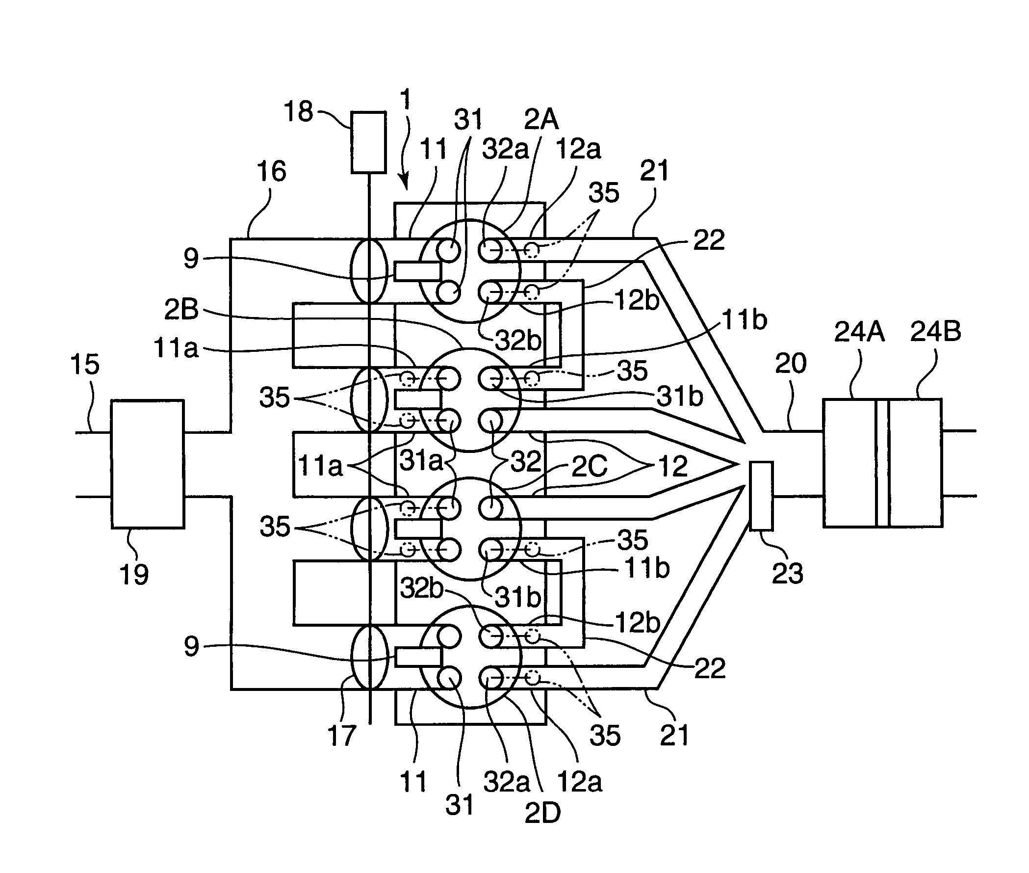
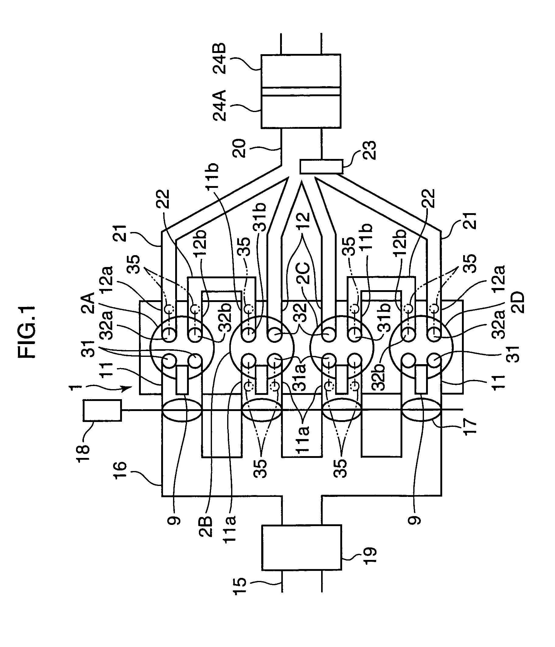
[0423]In the overall construction of the engine shown in FIG. 40, the main engine body, intake / exhaust ports, intake / exhaust passages connected thereto and the intake / exhaust valves that open...


PUM


Abstract

For the purpose of improving the fuel efficiency by lean combustion and enhancing the fuel efficiency improvement effects by performing compression ignition efficiently in some cylinders, a multi-cylinder spark ignition engine is constructed such that exhaust gas, that is exhausted from preceding cylinders 2A, 2D on the exhaust stroke side among pairs of cylinders whose exhaust stroke and intake stroke overlap in a low load, low rotational speed region, is directly introduced through an inter-cylinder gas passage 22 into following cylinders 2B, 2C on the intake stroke side and only gas exhausted from the following cylinders 2B, 2C is fed to an exhaust passage 20, which is provided with a three-way catalyst 24. Combustion controller is provided that controls the combustion of each of the cylinders such that combustion is conducted by forced ignition in a condition in which the air / fuel ratio is a lean air / fuel ratio which is larger by a prescribed amount than the stoichiometric air / fuel ratio in the preceding cylinders 2A, 2D and, in the following cylinders 2B, 2C, fuel is supplied to burnt gas of lean air / fuel ratio introduced from the preceding cylinders 2A, 2D and combustion is conducted by compression ignition.

Description

TECHNICAL FIELD[0001]The present invention relates to a control device for a spark ignition engine and in more detail relates to a device that controls the combustion condition in the cylinders of a multi-cylinder engine in order to improve fuel consumption and reduce emissions.BACKGROUND ART[0002]Techniques are previously known for improving fuel consumption in spark ignition engines by performing combustion under lean air / fuel ratio conditions, in which the air / fuel ratio of the mixture in the cylinders is larger than the stoichiometric air / fuel ratio (or theoretical air / fuel ration). For example, as illustrated in Laid-open Japanese Patent Application No. H. 10-274085, a technique is known in which an injection valve that injects fuel directly into the combustion chamber is provided and super-lean combustion is produced by conducting stratified charge combustion in the low rotational speed low load region etc. Specifically, such stratified charge combustion consists in altering t...

Claims


Application Information

Patent Timeline
Patent Type & Authority Patents(United States)
IPC IPC(8): F02B75/20F01L1/18F01L1/26F01L13/00F02B1/12F02B17/00F02B23/10F02B47/10F02B75/12F02B75/18F02D13/02F02D13/06F02D41/00F02D41/14F02D41/30F02D41/34F02F1/42F02M25/07F02P5/04F16N3/12
CPCF01L1/185F01L1/267F01L13/0005F01L13/0036F02B17/005F02B47/10F02B75/20F02D13/0215F02D13/0257F02D13/0261F02D13/06F02D41/0002F02D41/0057F02D41/008F02D41/1475F02D41/3017F02D41/3029F02D41/3035F02F1/4214F02M25/0743F02M25/0748F02M25/0749F02M25/0752F02P5/045F16N3/12F01L2800/00F01L2800/06F02B1/12F02B23/104F02B2075/125F02B2075/1816F02B2275/18F02D13/0265F02D41/1454F02D41/1456F02D41/187F02D2041/0017Y02T10/12Y02T10/146Y02T10/18Y02T10/123Y02T10/42Y02T10/47F02M26/01F02M26/37F02M26/42F02M26/43Y02T10/40F02D41/00F02D41/30
Inventor HITOMI, MITSUONISHIMOTO, TOSHIAKISHINYA, YOSHIYUKISUMIDA, KOUJIHAYASHI, TAKAYOSHIIWATA, NORIYUKIASANOMI, KOUJIYAMAUCHI, TAKETOSHIARAKI, KEIJI
Owner MAZDA MOTOR CORP
Why Eureka
Try Eureka