Method for X-ray reflectance measurement

a reflectance measurement and x-ray technology, applied in the direction of instruments, material analysis using wave/particle radiation, nuclear engineering, etc., can solve the problems of inability to carry out reflectance measurement with a high dynamic range, and inability to measure a weak x-ray intensity, etc., to achieve low noise level, high dynamic, and remarkable reduction of the total time required

Active Publication Date: 2007-05-22
RIGAKU CORP
View PDF3 Cites 3 Cited by
  • Summary
  • Abstract
  • Description
  • Claims
  • Application Information

AI Technical Summary

Benefits of technology

[0011]It is an object of the present invention to provide a method for X-ray reflectance measurement which can complete the measurement in a short time as around several seconds.
[0012]It is another object of the present invention to provide a method for X-ray reflectance measurement which can obtain a high-accuracy reflectance curve with a high dynamic range.
[0013]The present invention is characterized in that an X-ray reflectance is measured with the use of an X-ray detector having a high counting rate. The first aspect of the present invention has the feature that a desired dynamic range is assured even when the measuring time length per interval is very short. The second aspect of the present invention has the feature that an X-ray reflectance curve data is obtained with an extremely high dynamic range with the use of an X-ray detector having a very low noise level if the measuring time length per interval is set to be long enough.

Problems solved by technology

Besides, since the X-ray reflectance measurement often requires a five-digit dynamic range or over, it would be necessary to insert or remove an absorption plate in the middle of the measurement operation in the case of using the ordinary proportional counter or the scintillation counter having an upper-limit counting rate of not more than 106 cps, the insertion or removable of the absorption plate being an obstacle to the reduction of the measuring time.
Since the ordinary method uses the proportional counter or the scintillation counter as an X-ray detector, it is impossible to measure a weak X-ray intensity because of the inherent noise level of the X-ray detector and thus it is impossible to carry out the reflectance measurement with a high dynamic range.

Method used


Image

  • Method for X-ray reflectance measurement
  • Method for X-ray reflectance measurement
  • Method for X-ray reflectance measurement

Examples


Embodiment Construction

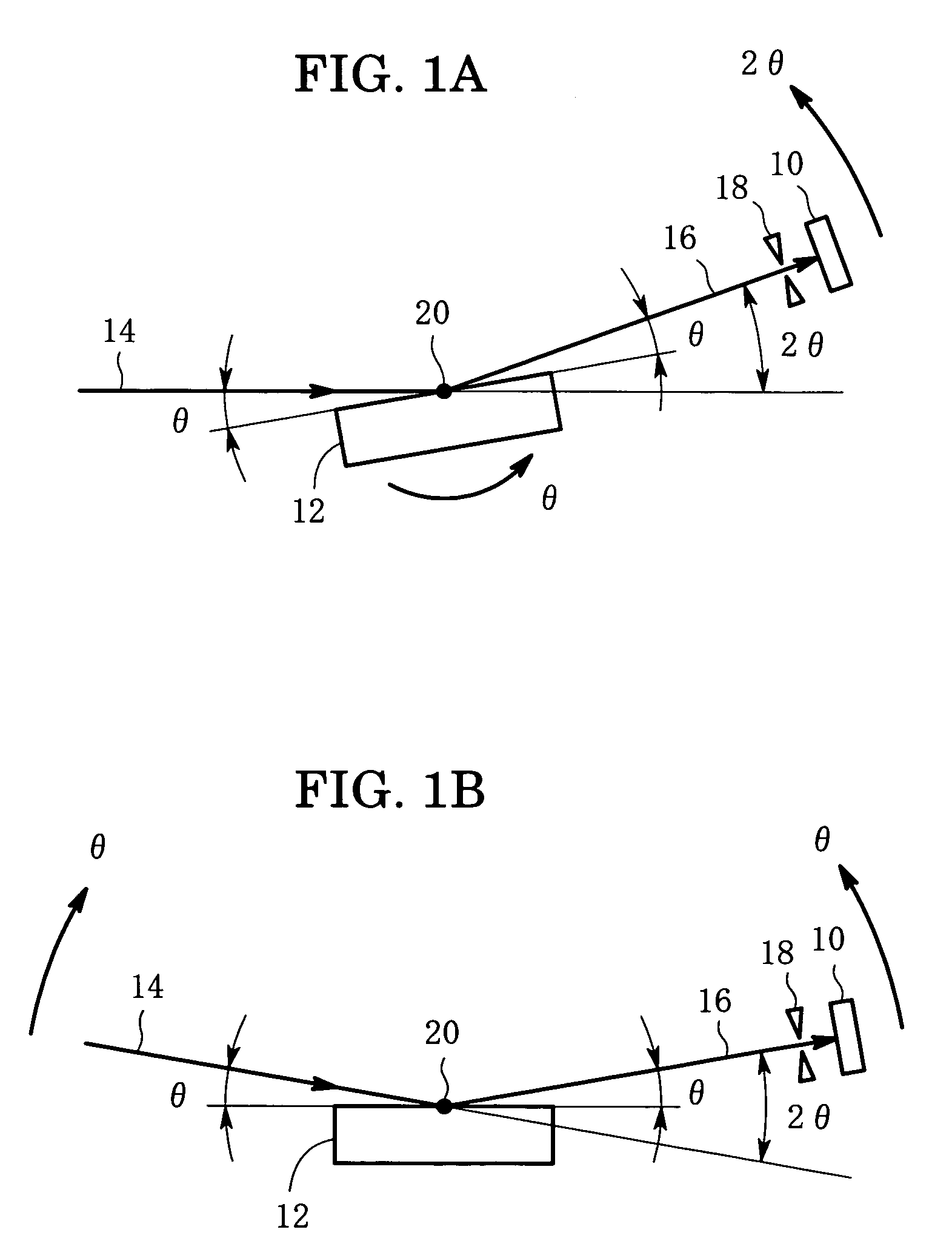
[0034]Embodiments of the present invention will now be described below with reference to the drawings. FIGS. 1A and 1B illustrate two arrangements of an optical system in a method for X-ray reflectance measurement according to the present invention. Referring to FIG. 1A, an X-ray detector 10 is an APD. An X-ray 14 is incident on the surface of a sample 12 at a small incident angle θ. An X-ray 16 reflected at the surface of the sample 12 passes through a receiving slit 18 and is detected by the APD 10, the slit 18 and the APD 10 being positioned at an outgoing angle θ from the surface of the sample 12. An assembly consisting of the receiving slit 18 and the APD 10 will be referred to as a receiving system hereinafter. An angle between the incident X-ray 14 and the reflected X-ray 16 is a scattering angle 2θ. The scattering angle 2θ is scanned in a manner that the sample 12 is rotated with a θ-rotation around the center 20 of a goniometer while the receiving system is rotated around t...


PUM

PropertyMeasurementUnit
scattering angle 2θaaaaaaaaaa
aaaaaaaaaa
scattering angle 2θaaaaaaaaaa

Abstract

An X-ray reflectance is measured with the use of an X-ray detector, which is not less than 107 cps in upper-limit counting rate and is not more than twenty cps in noise level, under the condition that a measuring time length per interval of scattering angle 2θ is not more than fifty milliseconds, so that the measurement of one reflectance curve is completed in a short time as several seconds. In another aspect of the invention, the X-ray detector used is not less than 107 cps in upper-limit counting rate and is not more than 0.01 cps in noise level, and the measuring time length per interval is not less than a hundred seconds, so that the X-ray reflectance curve is obtained with not less than a nine-digit dynamic range. The X-ray detector may be an avalanche photo diode.

Description

BACKGROUND OF THE INVENTION[0001]1. Field of the Invention[0002]The present invention relates to a method for measuring an X-ray reflectance in a short time with the use of an X-ray detector having a high upper-limit counting rate, and a method for measuring an X-ray reflectance with a high dynamic range with the use of an X-ray detector having a low noise level.[0003]2. Description of the Related Art[0004]It is known to measure an X-ray reflectance of a thin film and analyze the properties of the thin film, e.g., a film thickness, a density, a surface roughness and a boundary roughness, based on the measured data, as disclosed in Japanese patent publication No. 10-38821 A (1998), which will be referred to as the first publication.[0005]An X-ray reflectance curve can be determined in a manner that a reflected X-ray intensity is measured with the scanning of the scattering angle 2θ in a range between zero to five degrees for instance. If a reflected X-ray intensity is measured at 0.0...

Claims


Application Information

Patent Timeline
Patent Type & Authority Patents(United States)
IPC IPC(8): G01N23/20G01N23/207G01T1/24G21K5/02
CPCG01N23/20G01N23/085G01T1/242
Inventor OMOTE, KAZUHIKO
Owner RIGAKU CORP
Why Eureka
Try Eureka