Control and power module for integrated alternator-starter

a technology which is applied in the direction of electric generator control, dynamo-electric converter control, instruments, etc., can solve the problems of large size of control and power module, additional difficulty in assembly stage of motor vehicles, etc., and achieves the reduction of the length of the connection, the effect of high measurement accuracy and reduced length

Active Publication Date: 2007-05-29
VALEO EQUIP ELECTRIC MOTEUR
View PDF11 Cites 50 Cited by
  • Summary
  • Abstract
  • Description
  • Claims
  • Application Information

AI Technical Summary

Benefits of technology

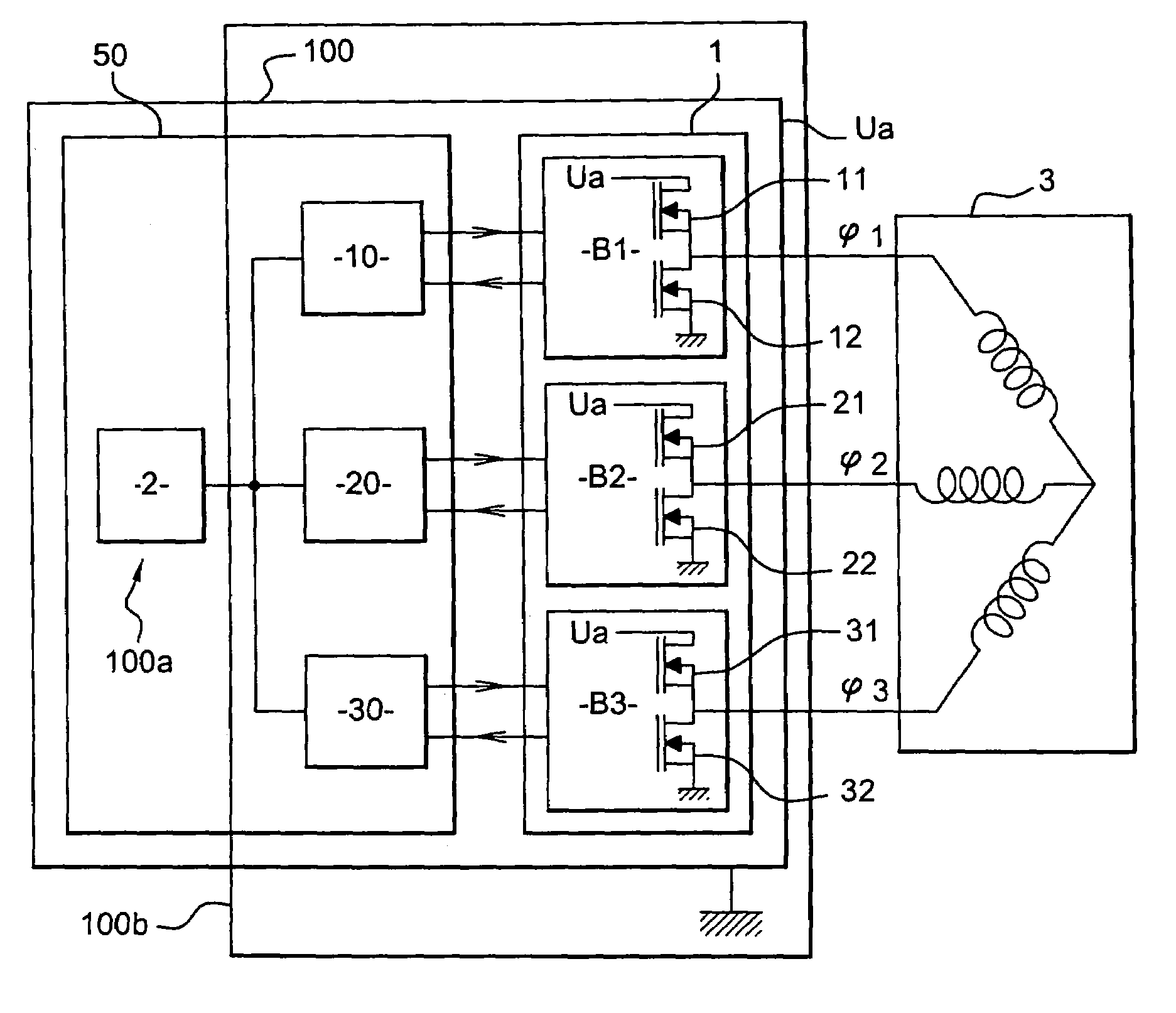
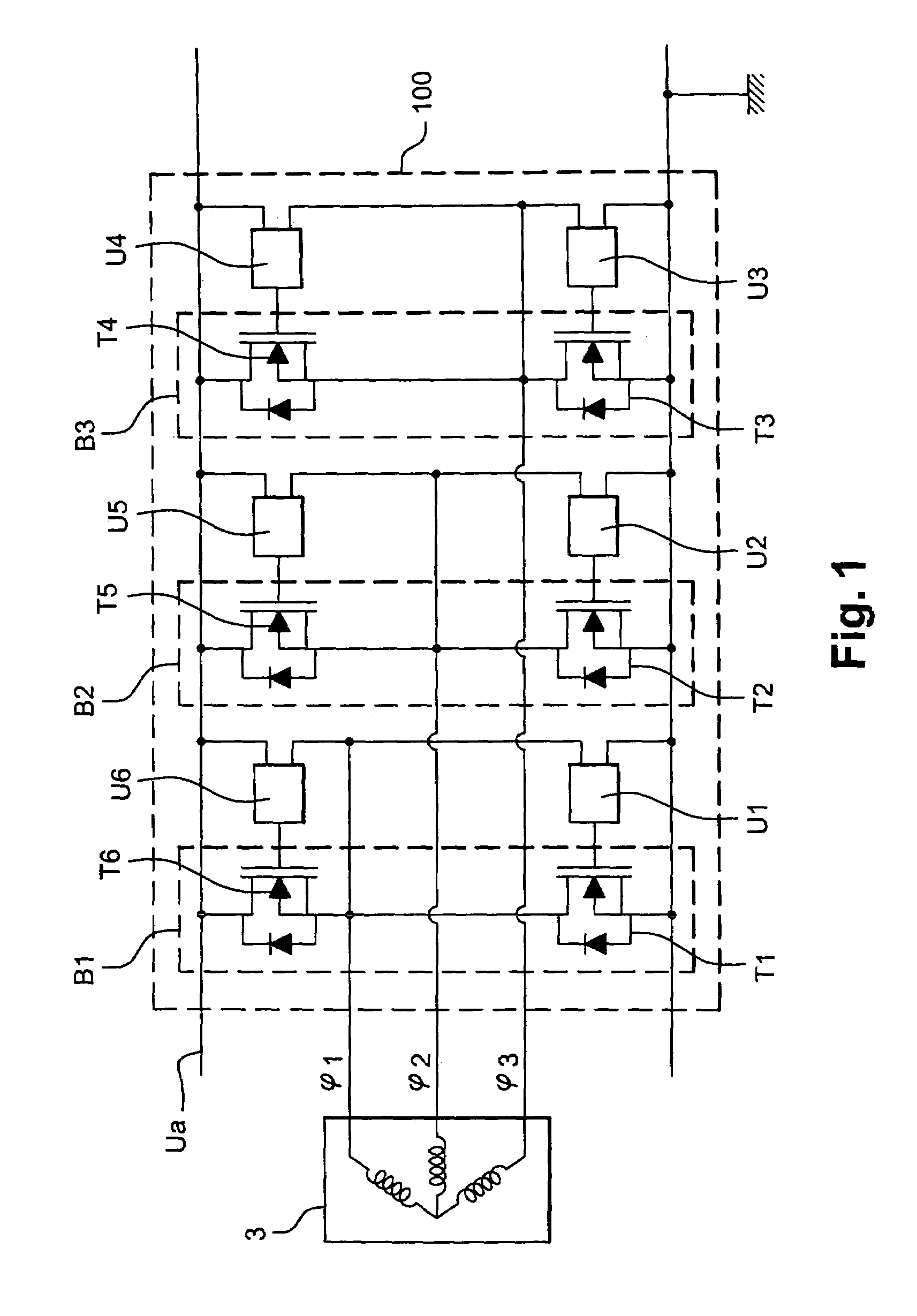
[0047]Thus the present invention has the advantage of reducing the length of the connection between the drivers and the power unit. Since some of these connections are used for measuring purposes, for example measurements of voltage occurring in the power unit, the reduction in length of these connections dedicated to measurements enables high measurement precision to be guaranteed by eliminating parasitic disturbances which could affect long connections.
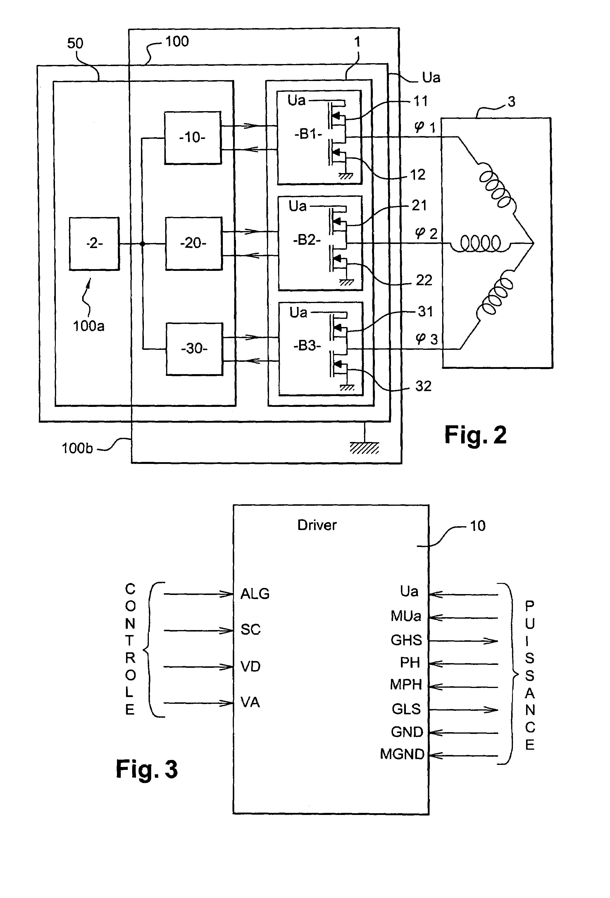
[0048]The driver of the control unit of the invention is able to control a plurality of transistors simultaneously, that is to say the transistors of a common branch of the rectifier bridge. This driver therefore has the advantage that it is very small, while at the same time containing a large number of functions. Because of its relatively small size, it can be located on the power stage, close to the transistors of the power unit which it controls.

Problems solved by technology

In consequence, the control and power module is relatively large in size, which makes it necessary to mount it in a casing which is separate from the casing that contains the electro-mechanical assembly of the alternator-starter.
In addition, for the user it involves an additional difficulty in the assembly stage of the motor vehicle, because it is for the motor manufacturer to connect the two casings together.

Method used


Image

  • Control and power module for integrated alternator-starter
  • Control and power module for integrated alternator-starter
  • Control and power module for integrated alternator-starter

Examples


first embodiment

[0157]In a first embodiment, as can be seen in FIGS. 9 and 10, bosses 123 are formed on the base. These bosses are adapted to receive the connecting wires 126 in constructing the power circuit. These connections are preferably of the wire bonding type. During the process of moulding the resin at the level of the metallic tracks, it will clearly be necessary to provide openings 124, free of resin, to enable the pads of the boss 123 to pass upwards. Similarly, the insulator 108, such as TVI mentioned above, will preferably have to be pressed out beforehand in order that it is able to be positioned around the pads 123. Such a configuration has the advantage that its connecting wires are very short.

[0158]In another version and as shown in FIG. 11, an aperture in the resin 107 and in the insulator 108 is formed in such a way as to reach the metallic base 109, constituting ground, directly. This solution enables the bosses 123 to be eliminated.

[0159]FIG. 12 illustrates one embodiment of a...

second embodiment

[0174]In the case where the dissipater is electrically insulated from the rear bearing plate of the machine, the dissipater constitutes an insulated ground which is connected to the ground of the battery directly or through the chassis of the vehicle. In this configuration, and in the second embodiment which consists in including the electronics in a single power module, as can be seen in FIG. 12, the ground pads 202a and 203a are omitted and are replaced by ground connections which are similar to those described with reference to FIGS. 9 to 11, and in which the base 109 will be replaced by the top face of the dissipater 113.

[0175]FIG. 13 shows a side view, in cross section, of the rear of an alternator-starter in which the electronics are integrated, having an arrangement of control and rectifying electronics according to the invention. As in all known alternator-starter machines, the machine shown in FIG. 13 has a rotor 743 fixed on a rotating shaft 502. The rotor 743 is surrounde...

first modified embodiment

[0227]In a first modified embodiment, the dissipater bridge 113 is fixed on the rear bearing plate 504 by means of assembly studs 527 which are electrically insulated and which are preferably non-conductors of heat, thereby constituting a thermal barrier against heat coming from the stator.

[0228]Preferably, the studs 527 are the same as those used for conventionally fixing the bearing plate 504 with the magnetic circuit 508 of the stator 503. An electrically insulating washer 527b is interposed between the fastening nut 527a and the top face 113a of the dissipater 113. A spacer 527c, having a shoulder 527d, is interposed between the lower face 113b of the dissipater and the axially outer face of the rear bearing plate 504.

[0229]In another modified version, the dissipater 113 is fixed with respect to the rear bearing plate 504 in an electrically insulated manner, by means of a screw 528, the head of which is oriented on the side of the lower axial face of the bearing plate 504. In th...


PUM


Abstract

The invention relates to a control and power module for an alternator-starter for a motor vehicle, connected between the alternator-starter (3), an on-board wiring network (Ua) and a ground line (GND) of the vehicle, and comprising:a transistor bridge with several branches (B1–B3), anda control unit for comparing a phase voltage (ψ) of the machine with a reference voltage (Ua, GND) and for controlling the transistors as a function of the result of the comparison,the control unit comprising:a driver (10, 20, 30) for each branch of the transistor bridge, the driver being connected close to the transistors of the branch, anda control circuit for controlling the drivers.

Description

FIELD OF THE INVENTION[0001]This invention relates to a rotary reversible electrical machine, such as an alternator-starter, which is adapted in particular, firstly to supply with electricity the on-board wiring network of a motor vehicle and to charge the battery of that vehicle, and secondly, to start the engine of the motor vehicle. More particularly, the invention relates to a control and power module adapted to control such a machine.STATE OF THE ART[0002]In a motor vehicle, the alternator converts rotary movement of the inductive rotor, driven by the engine of the vehicle, into an induced electric current in the windings of the stator. The alternator can also be reversible, and so constitute an electric motor, or rotary electric machine, which is arranged to drive the engine of the vehicle in rotation via the rotor shaft. This reversible alternator is called an alternator-starter, or starter-alternator. It enables mechanical energy to be converted into electrical energy and vi...

Claims


Application Information

Patent Timeline
Patent Type & Authority Patents(United States)
IPC IPC(8): H02P9/00F02N11/04H02K11/00F02N11/08H02K11/04
CPCF02N11/04F02N11/0859H02K11/048F02D2400/18F02N2011/0896H01L2224/48228H01L2224/48229H01L2224/48472H01L2224/49111H01L2224/49171H01L2224/45144H01L2924/13091H02K11/05H01L2924/00H02P9/30H02P9/08
Inventor PIERRET, JEAN-MARIEPFIFFER, JEAN JULIENTAUVRON, FABRICE
Owner VALEO EQUIP ELECTRIC MOTEUR
Why Eureka
Try Eureka