Steel pipe for embedding-expanding, and method of embedding-expanding oil well steel pipe

a technology of oil well steel pipe and steel pipe, which is applied in the direction of furnaces, heat treatment equipment, borehole/well accessories, etc., can solve the problems of increasing excavation costs, increasing the cost of excavation, and reducing the collapse resistance of embedded and expanded steel pipes, so as to promote the most bending of expanded pipes and small effect of steel pipe bending

Inactive Publication Date: 2007-06-05
NIPPON STEEL CORP
View PDF17 Cites 16 Cited by
  • Summary
  • Abstract
  • Description
  • Claims
  • Application Information

AI Technical Summary

Benefits of technology

[0047]As described above, the reason for the lowering of collapse strength is the fact that the roundness of the pipe remarkably deteriorates and a synergistic effect of both the non-uniform wall thickness and the deterioration of the roundness lowers the collapse strength, when the non-uniform wall thickness ratio of the expanded pipe exceeds 25 or 30 . Further, in a high pipe expansion ratio of 30 or more, when the non-uniform wall thickness ratio of expanded pipe exceeds 10 or more, the lowering of collapse strength is remarkably increased. In order to maintain 0.80 or more of the “actually measured collapse strength / collapse strength of the pipe without non-uniform wall thickness”, the non-uniform wall thickness ratio of the expanded pipe should be set to 30 or less.

Problems solved by technology

Therefore, in order to excavate a deep well for embedding oil well pipes, the excavating area must be increased, resulting in increased cost for excavation.
However, the above-mentioned embedding-expanding method has the following problems.
One of the problems is that the embedded and expanded steel pipe has remarkably lowered collapse resistance to the external pressure in the ground.
This means lowering of its collapse strength.
Another problem is that the expanded pipe generates bending.
Non-uniformity of the wall thickness exists unavoidably in the steel pipe.
The non-uniformity of the wall thickness means non-uniformity of the wall thickness in the cross-section of the pipe.
This phenomenon leads to a decrease in collapse strength.
Further, the thick wall portion and the thin wall portion of the pipe generate different amounts of expansion in the circumferential direction of the pipe during the expanding process, resulting in different amounts of shrinkage in the longitudinal direction of the pipe.
When a casing or tubing is bent, non-uniform stress is applied to a screwed portion, which is the joint portion between pipes, so that gas may leak.

Method used


Image

  • Steel pipe for embedding-expanding, and method of embedding-expanding oil well steel pipe
  • Steel pipe for embedding-expanding, and method of embedding-expanding oil well steel pipe
  • Steel pipe for embedding-expanding, and method of embedding-expanding oil well steel pipe

Examples


example 1

[0111]Four kinds of steels, having chemical compositions shown in Table 1, were prepared, and seamless steel pipes having an outer diameter of 139.7 mm, a wall thickness of 10.5 mm and a length of 10 m were produced in the usual Mannesmann-mandrel pipe production process. Then, the steel pipes were subjected to heat treatment of quenching-tempering to make them products corresponding to API-L80 grade (yield strength: 570 MPa).

[0112]Non-uniform wall thickness ratios of non-expanded steel pipes of Steel A, Steel B and Steel C were measured by UST. After that the steel pipes were expanded by mechanical drawings with a plug inserted in the pipe. The pipe expansion ratios were three degrees of 10%, 20% and 30% as a magnification ratio on the inner diameter of the pipe.

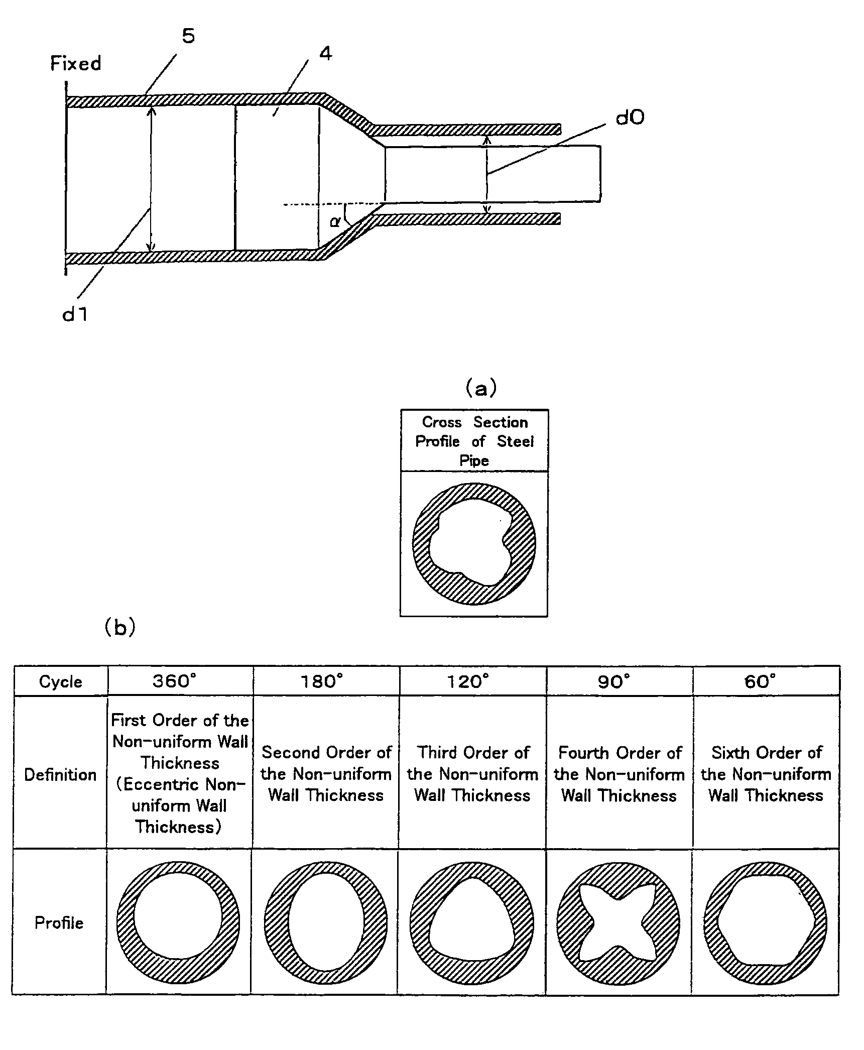
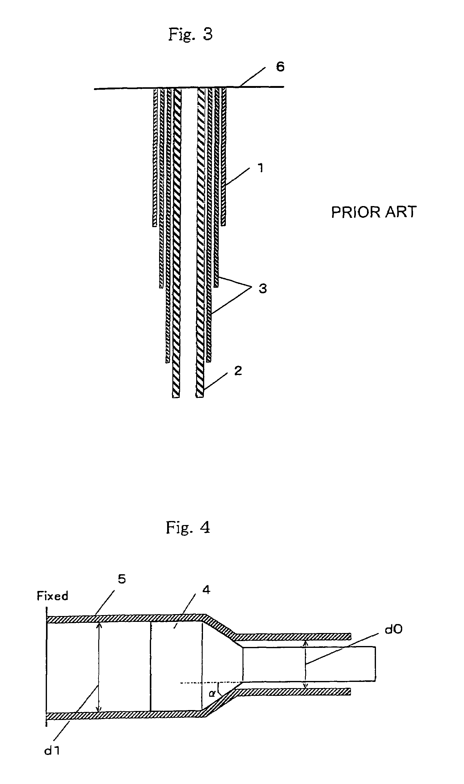
[0113]FIG. 4 is a cross-sectional view of a plug periphery during the expansion of the pipe. As shown in FIG. 4, the pipe 5 was expanded by fixing an end of the expansion starting side and mechanical drawing of the plug 4. ...

example 2

[0118]Using the Steel D in Table 1, a seamless steel pipe having an outer diameter of 139.7 mm, a wall thickness of 10.5 mm and a length of 10 m was produced by the same method as in the Example 1, and subjected to heat treatment of quenching-tempering. The obtained pipe is a product corresponding to API-L80 grade.

[0119]The non-uniform wall thickness profile of the steel pipe, before expanding, was investigated by UST. As shown in FIG. 7, the non-uniform wall thickness profile was obtained by measuring wall thickness at 16 points equally divided in the circumferential direction of the pipe with respect to every 10 cross sections at 500 mm pitches in the longitudinal direction of the pipe. From the wall thickness profile, the components of the eccentric non-uniform wall thickness (the first order of the non-uniform wall thickness), the second order of the non-uniform wall thickness and the third order of the non-uniform wall thickness were extracted by the Fourier analysis to obtain ...


PUM

PropertyMeasurementUnit
thicknessaaaaaaaaaa
thicknessaaaaaaaaaa
thicknessaaaaaaaaaa

Abstract

(1) A steel pipe that is expanded radially in a state wherein it was inserted in a well such as an oil well, characterized in that the non-uniform wall thickness ratio E0 (%) before expanding satisfies the following expression ①.E0≦30 / (1+0.018α)①Wherein α is the pipe expansion ratio (%) calculated by the following expression ②.α=[(inner diameter of the pipe after expanding−inner diameter of the pipe before expanding) / inner diameter of the pipe before expanding]×100②(2) A steel pipe that should be expanded radially in a state wherein it is inserted in a well, such as an oil well, characterized in that the eccentric non-uniform wall thickness ratio is 10% or less.When the embedding-expanding method is performed with use of the steel pipe of (1) or (2), lowering of collapse strength of the expanded steel pipe is prevented and bending thereof can be decreased.

Description

[0001]This application is a continuation of International Patent Application No. PCT / JP02 / 02261, filed Mar. 11, 2002. This PCT application was not in English as published under PCT Article 21 (2).TECHNICAL FIELD[0002]The present invention relates to a steel pipe, which is embedded in an oil well or a gas well, which is collectively referred to as only an “oil well” hereinafter, and a method of embedding oil well steel pipes.BACKGROUND ART[0003]When oil well pipes are embedded from the surface of the earth to an underground oil field, excavation is first performed to provide a well having a predetermined depth and then an oil well pipe, which is called “casing”, is embedded in the well in order to prevent the wall of the well from crumbling. Further excavation is performed from the front end of the casing to produce a deeper well, and then a new pipe for casing is embedded through the previously embedded casing. By repeating such operations, pipes, which are used in an oil field, are...

Claims


Application Information

Patent Timeline
Patent Type & Authority Patents(United States)
IPC IPC(8): E21B43/10C22C38/00E21B29/00B21B39/20B21C1/24C21D9/08C22C38/02C22C38/04C22C38/12C22C38/22C22C38/28E21B7/20
CPCB21C1/24C21D9/085C22C38/02E21B43/103C22C38/12C22C38/22C22C38/04
Inventor ARAI, YUJIKONDO, KUNIOAMAYA, HISASHIYAMANE, AKIHITO
Owner NIPPON STEEL CORP
Why Eureka
Try Eureka