

Stent with variable properties
a variable-property stent technology, applied in the field of intraluminal medical devices, can solve the problems of reducing the flexibility of the stent, negatively affecting the delivery of the stent in the vasculature of the patient, and it is difficult to accurately visualize the stent, etc., to achieve excellent fluoroscopic properties or mri properties, high radiopacity, and increased flexibility
- Summary
- Abstract
- Description
- Claims
- Application Information
AI Technical Summary
Benefits of technology
Problems solved by technology
Method used
Image

Examples
Embodiment Construction
[0060]While this invention may be embodied in many different forms, there are described in detail herein specific preferred embodiments of the invention. This description is an exemplification only of the principles of the invention, and is not intended to limit the scope of the invention to the particular embodiments illustrated and described herein.
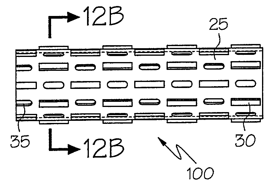
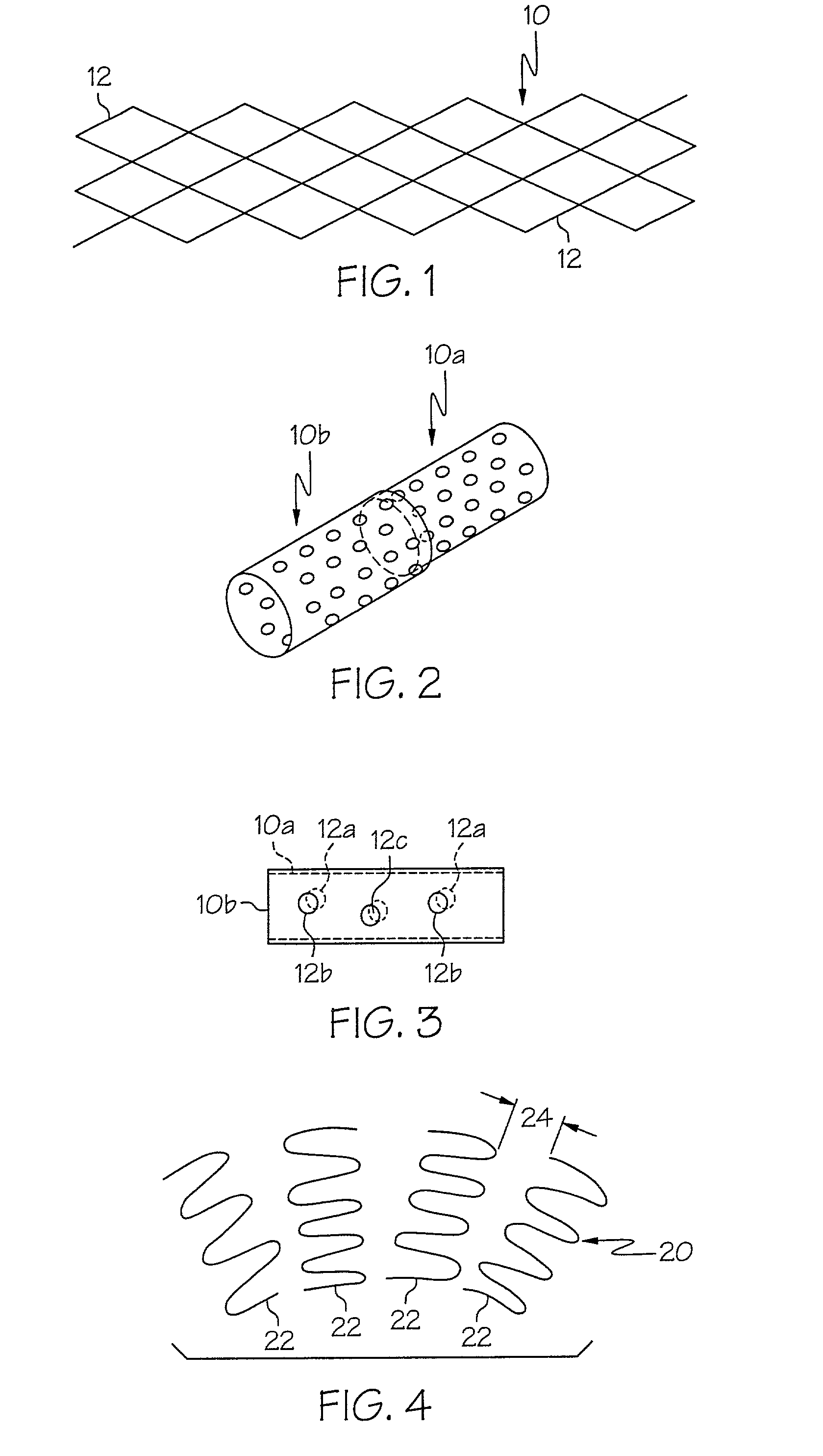
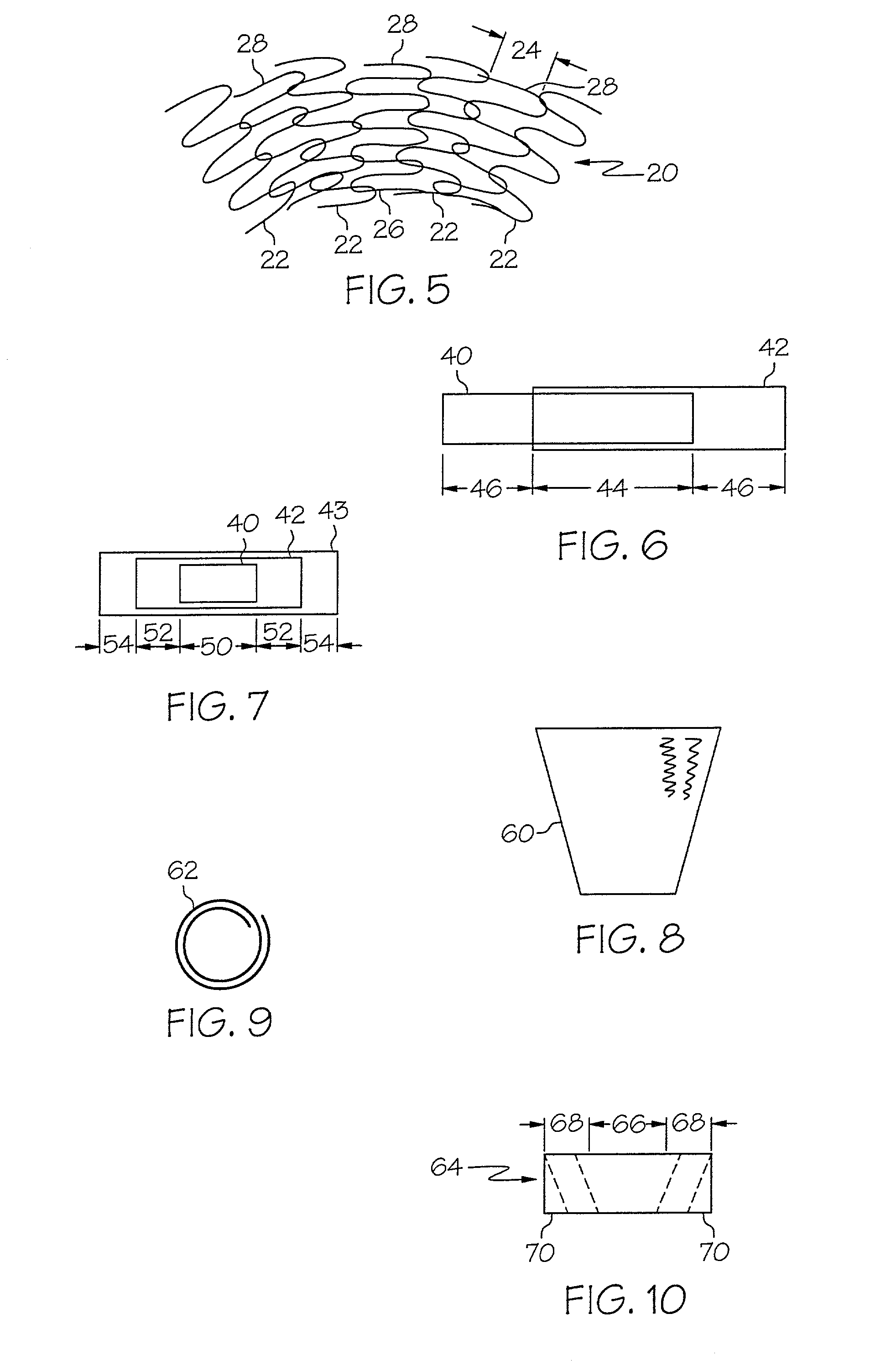
[0061]In some embodiments, the present invention includes a micro porous stent having a deformable structure. Generally, this is meant that the deformable struts of both self-expanding and mechanically-expandable stents already known in the art should be provided with micro porous structure. The fabrication of such stents is typically from flat sheet which is rolled then welded into a cylinder or from tubular stock.
[0062]A first way to achieve micro structure in a stent involves simply making the struts and the openings of the stent extremely small. Such a stent would be comprised of a plurality of interconnected deformable struts arran...
PUM
 Abstract
Description
Claims
Application Information