Disc drive apparatus and motor driver circuit

a disc drive and motor technology, applied in the direction of motor/generator/converter stopper, electronic commutator, dynamo-electric converter control, etc., can solve the problems of incomplete soft switch control, serious problems, and rise in noise, so as to reduce the noise, reliably reduce the noise of the motor, and realize soft switch control. the effect of

Inactive Publication Date: 2007-06-05
SONY CORP
View PDF9 Cites 6 Cited by
  • Summary
  • Abstract
  • Description
  • Claims
  • Application Information

AI Technical Summary

Benefits of technology

[0016]Thus, according to the present invention, the first drive voltage control means controls the highest value of the first drive voltage before the timing of phase-switching and the second drive voltage control means controls the highest value of the second drive voltage after the timing of phase-switching so that consequently it is possible to reliably realize soft switching control when driving the motor at high speed. Thus, it is possible to reliably reduce noises produced as a result of driving the motor to rotate.
[0017]According to the present invention, the down-counting means of the first drive voltage control means controls the largest value of the first drive voltage by counting a plurality of counts per clock of a predetermined clock frequency and the up-counting means of the second drive voltage control means controls the largest value of the second drive voltage by counting a plurality counts per clock of a predetermined frequency. Thus, with this time, it is possible to hold the clock frequency of the circuit low when the motor is driven to rotate at high speed and, at the same time reduce the noise that arises as a result of soft switching control when the motor is driven to rotate at high speed.
[0018]A motor driver circuit according to the invention comprises a plurality of timing signal generation means for generating respectively a plurality of different timing signals for determining timings of phase-switching the motor and a drive voltage control means for controlling the highest values of the drive voltages for driving the motor respectively according to the plurality of different timing signals. Thus, if motor driver circuits according to the invention are manufactured with variances in the manufacturing process, each circuit can drive a motor appropriately to accommodate the variance and realize soft switching control when driving the motor to rotate so that it is possible to reliably reduce the noise of the motor.

Problems solved by technology

Noises arise to give rise to problems in apparatus such as portable MD (Mini Disc: tradename) apparatus comprising a rotary drive system for driving a disc to rotate when the spindle motor of the rotary drive system is operated.
Particularly, in the case of the PWM (pulse width modulation) system of directly supplying a pulse wide modulation signal to a spindle motor and driving the motor to rotate, noises that arise due to abrupt fluctuations of electric current at the time of a phase-switching action give rise to serious problems.
However, if soft switching control is used when driving a spindle motor to rotate by means of a direct PWM system as disclosed in the Patent document 1 and, for instance, the master clock frequency of the motor control circuit of the motor is held low in order to suppress the power consumption rate while the spindle motor is driven to rotate at a high rate, there arise various problems including that the soft switch control is incomplete and the noise of the motor cannot be reduced significantly and that the PWM control is incomplete and it is not possible to supply an electric current at a rate sufficient for driving the spindle motor at high speed.
While the technique of the Patent Document 2 can be used to appropriately control the operation of driving a spindle motor to rotate by switching the mode of operation according to the rotary speed of the spindle motor (a mode for using a first timing signal and a mode for using a second timing signal), it is accompanied by a problem that it is not compatible with soft switching control for reducing the noise of the spindle motor.

Method used


Image

  • Disc drive apparatus and motor driver circuit
  • Disc drive apparatus and motor driver circuit
  • Disc drive apparatus and motor driver circuit

Examples


case 1

[0120] This refers to a situation that frequently appears when the master clock frequency of the motor controller 15 is held low in order to suppress the power consumption rate and the spindle motor 3 is driven to rotate at high speed. The processing operation for ΔLim overflows from the period of the transitional time Tvrlm (=transitional time Tvrvs) as shown in FIG. 15 and a phase-switching operation is conducted before the limiter value gets to “0”. Therefore, it is not possible to appropriately realize soft switching control in a situation of Case 1.

case 2

[0121] This refers to a situation where the timing of phase-switching agrees with the timing for the limiter value to get to “0”. Hence, it is possible to appropriately realize soft switching control.

case 3

[0122] This refers to a situation that frequently appears when the rotary speed of the spindle motor 3 is changed. The processing operation for ΔLim is terminated before the transitional time Tvrlm ends as shown in FIG. 16 so that the timing of phase-switching does not agree with the timing for the limiter value to get to “0”. Therefore, it is not possible to appropriately realize soft switching control in a situation of Case 3.

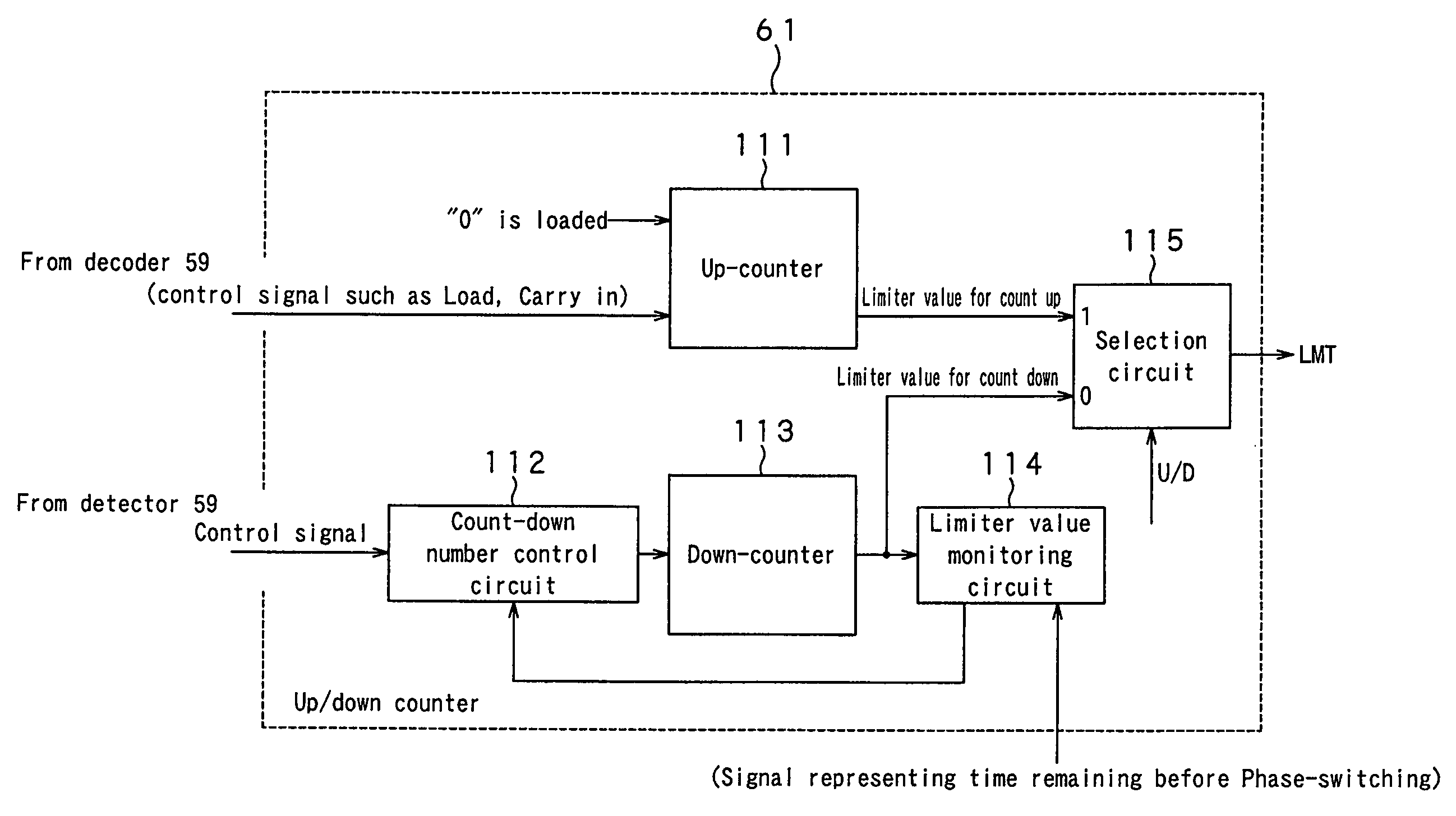
[0123]It will be clear from the above description that control signal LMT can be generated in a manner as described for Case 1 or Case 3 by means of a conventional up / down counter so that it is not possible to appropriately realize soft switching control.

[0124]Additionally, when the up / down counter comprises only a single up / down counter as described above by referring to conventional up / down counters and the spindle motor 3 is driven to rotate at high speed, the limiter value for a count up period and the limiter value for a count down period can overlap wit...


PUM

PropertyMeasurementUnit
drive voltageaaaaaaaaaa
voltageaaaaaaaaaa
clock frequencyaaaaaaaaaa

Abstract

A motor driver circuit according to the present invention comprises an edge signal generation means for generating an edge signal indicating the timing of phase-switching according to the values of a plurality voltages induced when driving the motor and a drive voltage control means for controlling the highest value of the drive voltage for driving the motor according to the edge signal. The drive voltage control means includes a first drive voltage control means for controlling the highest value of the drive voltage before the timing of phase-switching and a second drive voltage control means for controlling the highest value of the drive voltage after the timing of phase-switching. With this arrangement, it is possible to realize soft switching control while the motor is driven to rotate at high speed and reduce the noise due to the motor being driven to rotate.

Description

CROSS REFERENCES TO RELATED APPLICATIONS[0001]The present invention contains subject matter related to Japanese Patent Application JP 2004-176149 filed in the Japanese Patent Office on Jun. 14, 2004, the entire contents of which being incorporated herein by reference.BACKGROUND OF THE INVENTION[0002]1. Field of the Invention[0003]This invention generally relates to the technology of driving a motor to rotate by means of a direct PWM (pulse width modulation) system. More specifically, it relates to a technique of reducing the noise of a motor for rotating a disc by means of a direct PWM system in a disc drive apparatus for driving a disc mounted in it.[0004]2. Description of the Related Art[0005]Noises arise to give rise to problems in apparatus such as portable MD (Mini Disc: tradename) apparatus comprising a rotary drive system for driving a disc to rotate when the spindle motor of the rotary drive system is operated. Particularly, in the case of the PWM (pulse width modulation) sy...

Claims


Application Information

Patent Timeline
Patent Type & Authority Patents(United States)
IPC IPC(8): H02P6/18G11B19/28H02P1/54H02P6/06H02P6/08H02P6/182H02P6/21
CPCG11B19/28
Inventor TAKAYAMA, SEIRYUKOBA, KOUYA
Owner SONY CORP
Why Eureka
Try Eureka