Image writing apparatus and color image forming apparatus

a writing apparatus and color image technology, applied in the field of image writing apparatus, can solve the problems of shifts between, affecting the quality of output images, and affecting the accuracy of output images, so as to reduce the dot positional shift

Inactive Publication Date: 2007-06-05
CANON KK
View PDF6 Cites 4 Cited by
  • Summary
  • Abstract
  • Description
  • Claims
  • Application Information

AI Technical Summary

Benefits of technology

[0026]It is an object of the present invention to provide a color image forming apparatus which, over the entire scanning region on the surface of an image carrier, reduces dot positional shift in the sub-scanning direction or / and the main scanning direction, and enables to obtain a satisfactory color image containing only a small shift component in the sub-scanning direction or / and main scanning direction to be obtained.

Problems solved by technology

If this relative alignment of the spot positions is not achieved, upon overlapping on the conveyor belt., a color shift causes a decrease in quality of the output image.
In an actual optical scanning apparatus, however, shifts between these dot positions are caused by accuracy errors of the individual optical parts, accuracy errors of the individual mechanical components for assembling the optical parts, such as an optical box, assembly errors of the optical parts, and relative positional errors between the optical scanning apparatus and the image carrier.
Usually, however, the plurality of optical scanning apparatuses have different errors, and this is a factor causing color shift.
The amount of inclination differs between the two colors in FIG. 16, because there are variations in the error components, such as a single-unit accuracy error and an assembly error.
Actually, however, there are variations in all error factors, and this causes color shifting.
In FIG. 18, the amount of curvature differs between the two colors because there are variations in the error components, such as single-unit accuracy error and assembly error.
Actually, however, all the error factors contain variations, causing color shift.
In this adjustment method, however, it is necessary to bend the mirror itself by applying a large stress because of the low sensitivity of the mirror to scanning line curvature, and assembly accuracy, environmental changes, and the adjustment accuracy itself are problematic.
One of the most important factors causing scanning line curvature is the single-unit accuracy error of the lens.
However, in the mold Z of FIG. 19, for example, frames and parts forming the cavities A, B, C and D having identical optical characteristics contain manufacturing errors including assembly errors with the mold.
Because there occur delicate differences in the forming conditions between cavities, these factors cause accuracy errors in the four lenses formed.
The face apex height in the sub-scanning direction of the thus formed four lenses A, B, C and D may have single-unit accuracy errors, such as a curvature, along the main scanning direction, as shown in FIG. 21, and the single-unit accuracy error may often differ for the four lenses A, B, C and D. The occurrence of such single-unit accuracy errors causes refraction of a beam passing through the lens in the sub-scanning direction, and would cause scanning line curvature on the scanned surface.
The single-unit accuracy error of a lens is similarly a factor causing a partial magnification error in the main scanning direction.
For example, when a geometric surface error from the design shape of the second face (emitting face) of the lens is as shown by a thick line in FIG. 22, and upon drawing dots at equal intervals on the scanned surface, there is an interval error as compared with an ideal interval, i.e., a partial magnification error.

Method used


Image

  • Image writing apparatus and color image forming apparatus
  • Image writing apparatus and color image forming apparatus
  • Image writing apparatus and color image forming apparatus

Examples


first embodiment

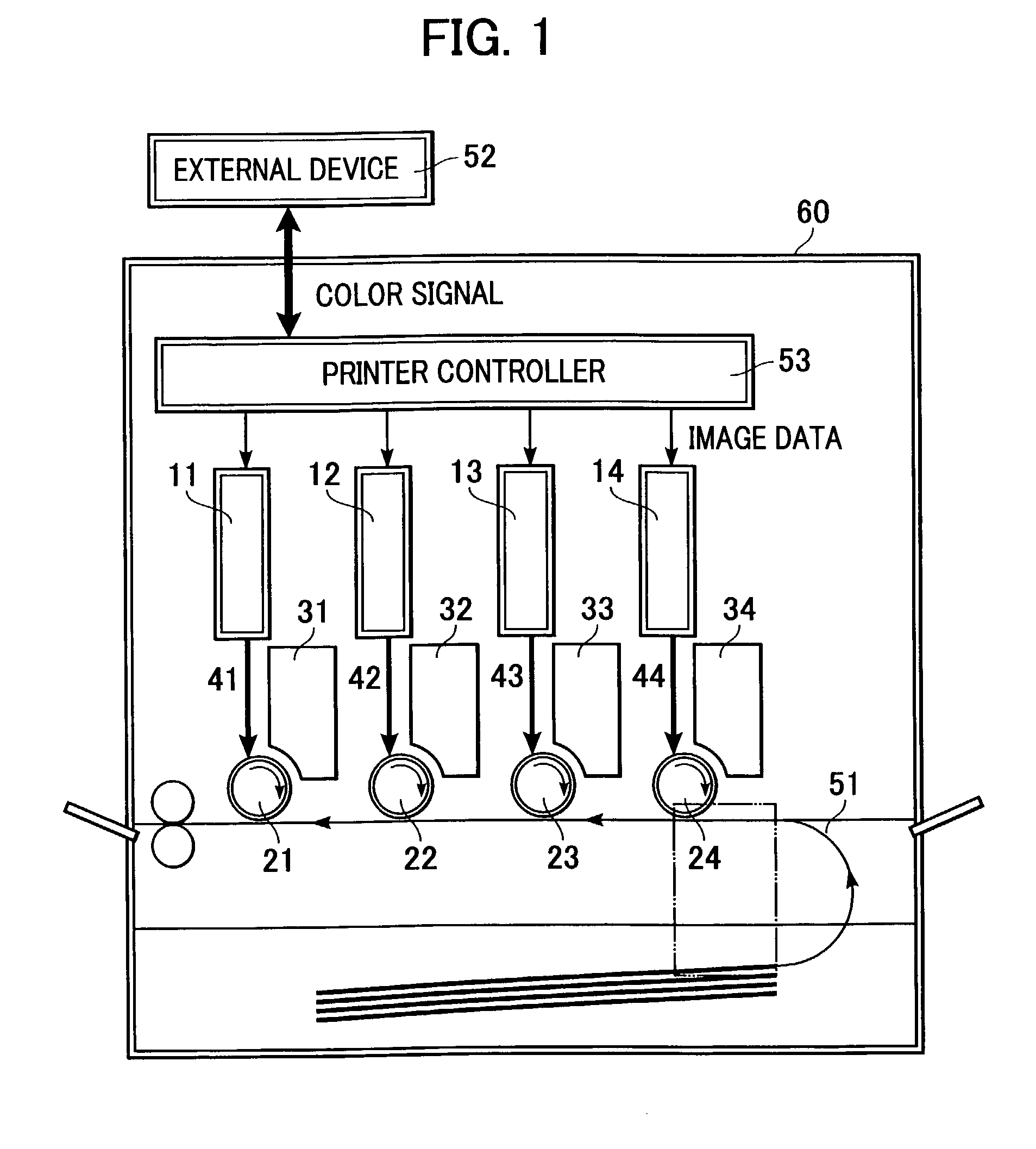
[0067]FIG. 1 is a partial schematic view of a color image forming apparatus of a first embodiment of the present invention. This embodiment covers a tandem-type color image forming apparatus in which four scanning optical apparatuses are arranged, and image information is recorded in parallel on the surfaces of photosensitive drums serving as image carriers.

[0068]An image writing apparatus of the present invention is defined as having a plurality of optical scanning apparatuses.

[0069]In the present invention, a plurality of optical scanning apparatuses may be separately arranged in the image writing apparatus, or they may be integrally arranged.

[0070]In this embodiment, the image writing apparatus holds / contains four optical scanning apparatuses arranged in parallel with each other.

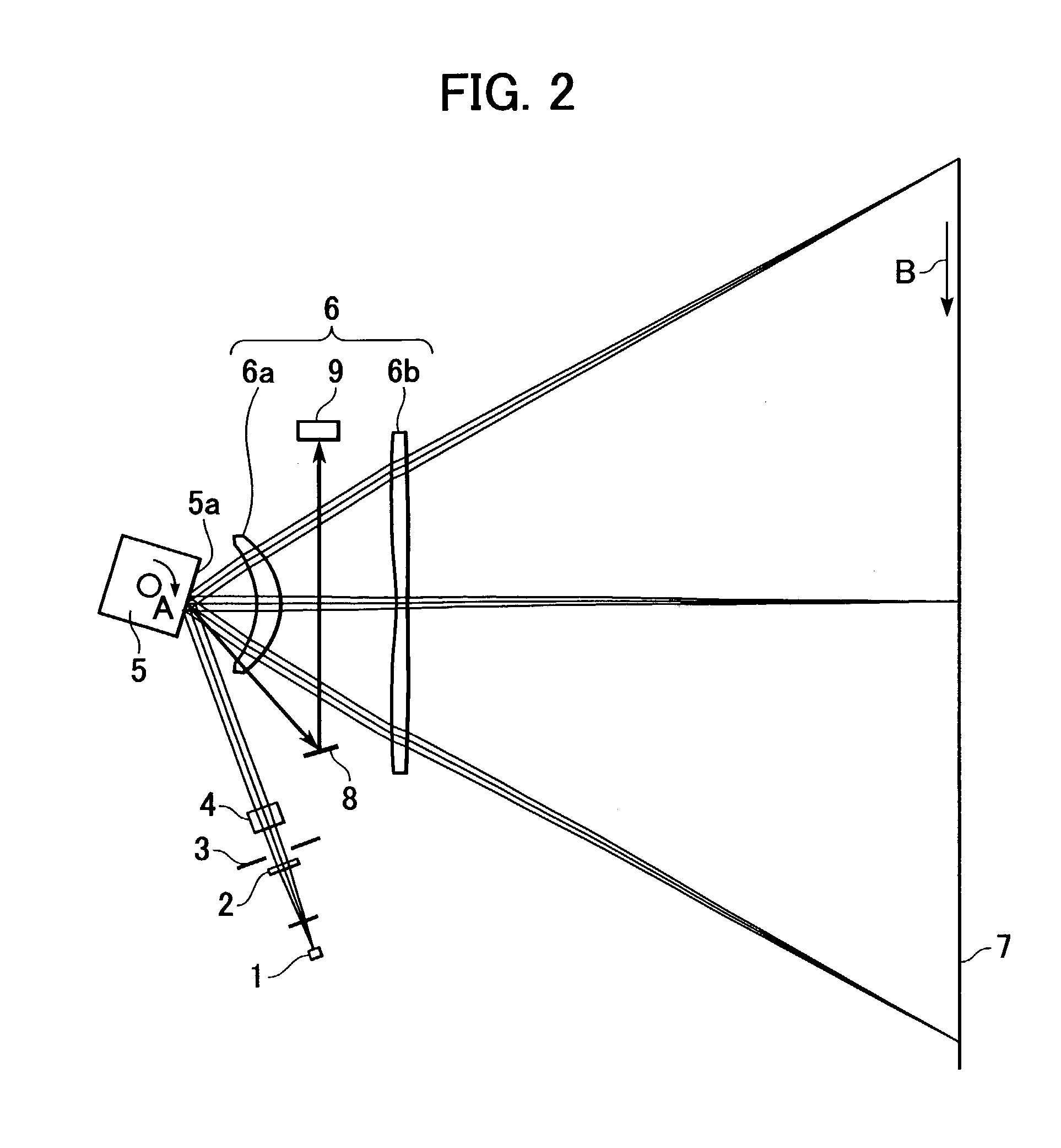
[0071]The direction in which the beam is reflected and deflected (deflection scanning) by deflecting means is defined as the main scanning direction, and the direction perpendicular to the optical axis of...

second embodiment

[0097]A second embodiment of the present invention will now be described. Differences from the above-mentioned first embodiment will mainly be described.

[0098]In this embodiment, when dividing the cavities into a plurality of groups so that a relative difference in optical parameters is within an allowable range, according to variations in the optical parameters (amount of scanning line curvature) caused by the cavity difference of lenses formed with a plurality of cavities, a lens used in a color image forming apparatus is selected from cavities of one of these groups. Any of these plurality of groups has at least one cavity belonging to all the plurality of groups.

[0099]In this embodiment, more specifically, the second scanning lens 6b, for example, from among the first and second scanning lenses 6a and 6b forming the scanning lens system 6 arranged in each of the scanning optical apparatuses is formed by using a plurality of cavities E, F, G, and H shown in FIG. 20. For the cavit...

third embodiment

[0103]A third embodiment of the present invention will now be described. Differences from the aforementioned first embodiment will mainly be described.

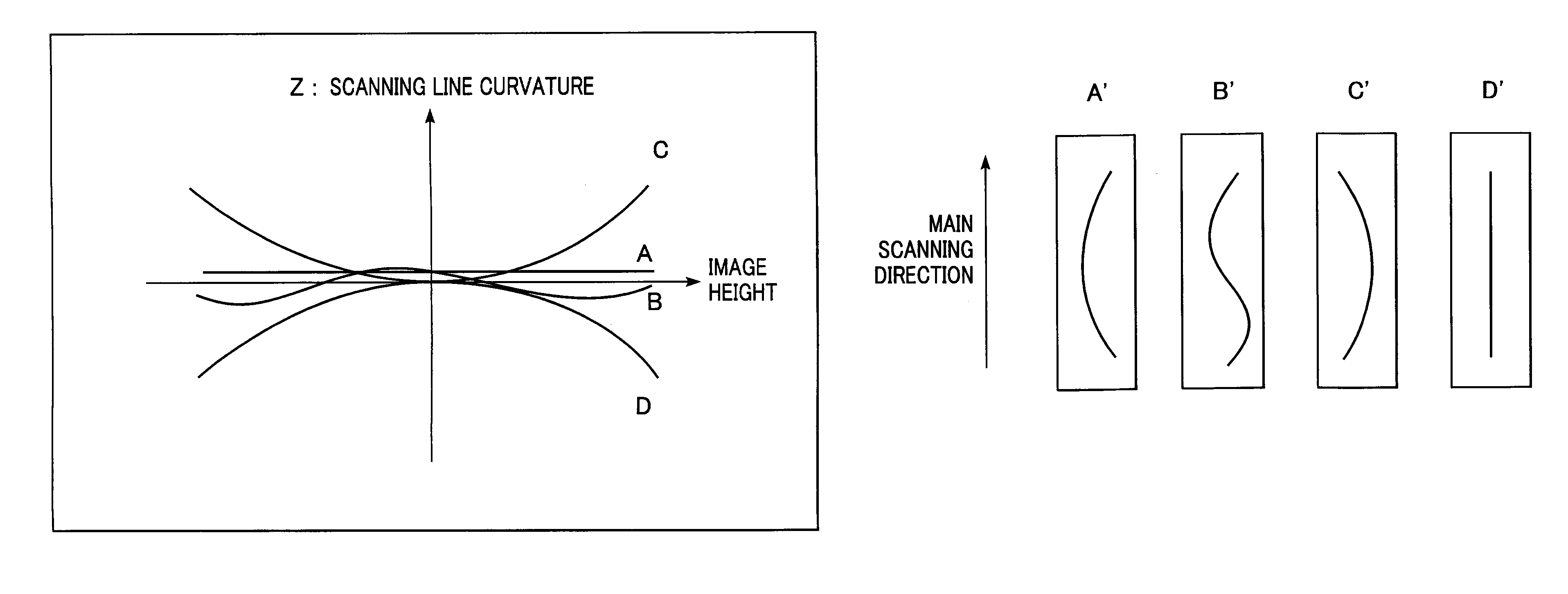
[0104]In this embodiment, from among the first and second scanning lenses 6a and 6b forming a scanning lens system 6 arranged in each optical scanning apparatus, the second scanning lens 6b is formed with a plurality of cavities A, B, C, and D shown for example in FIG. 19, and as shown in FIG. 21, the face apex height in the sub-scanning direction has a single-unit accuracy error such as curvature along the main scanning direction.

[0105]The first scanning lens 6a is also formed with a plurality of cavities A′, B′, C,′ and D′, and as shown in FIG. 6, the face apex height in the sub-scanning direction has a single-unit accuracy error such as curvature along the main scanning direction.

[0106]Regarding the curving direction of the scanning line curvature caused by a cavity difference of the first and second scanning lenses 6a and 6b forme...


PUM


Abstract

The present invention provides a color image forming apparatus forming an image by using a plurality of image carriers, wherein at least one lens having identical optical characteristics and forming individual scanning optical systems which scan the individual image carriers with beams is formed by use of a plurality of cavities. When dividing the cavities into a plurality of groups in response to variations in the optical characteristics caused by cavity difference of the lenses formed with the plurality of cavities so that the relative differences in an optical parameters are within an allowable range, at least one lens of each scanning optical system is selected from the cavities of one of the plurality of groups.

Description

BACKGROUND OF THE INVENTION[0001]1. Field of the Invention[0002]The present invention relates to an image writing apparatus. More particularly, the invention relates to an image writing apparatus suitable for use as a color forming apparatus such as a color laser beam printer, a color digital copying machine, or a multi-function printer.[0003]2. Description of the Related Art[0004]In scanning optical apparatuses such as laser beam printers, color digital copying machines or multi-function printers, it is the conventional practice to record an image by periodically causing deflection of a beam, which is optically modulated or emitted in response to an image signal from a light source, by using an optical deflector comprising, for example, a rotating polygon mirror, and conveying the deflected beam into a spot on the surface of a photosensitive recording medium (photosensitive drum) by a scanning lens system (scanning optical system) having an fθ characteristic, to optically scan the ...

Claims


Application Information

Patent Timeline
Patent Type & Authority Patents(United States)
IPC IPC(8): B41J27/00B41J2/44B41J2/47G02B13/00G02B26/10G03G15/01H04N1/113
CPCB41J2/473
Inventor TOYODA, KOJI
Owner CANON KK
Why Eureka
Try Eureka