Method and system for providing beam polarization

Active Publication Date: 2007-06-05
API TECH
View PDF6 Cites 36 Cited by
  • Summary
  • Abstract
  • Description
  • Claims
  • Application Information

AI Technical Summary

Benefits of technology

[0011]The present invention may also include a method for providing at least one of radiation polarizer and beam control. The method may include the steps of communicatively coupling at least one anti-reflection coating layer to a substrate, communicatively coupling at least two nanostructures to at least one of the at least one anti-reflection coating layer, providing interstitially to a respective one of the at least two nanostructures at least two groove layers, coupling the at least two groove layers and the at least two nanostructures to provide a pass wavelength in the range of about 250 nm to less than about a microwave wav

Problems solved by technology

This has been, as is known in the art, a limitation on the ty

Method used


Image

  • Method and system for providing beam polarization
  • Method and system for providing beam polarization
  • Method and system for providing beam polarization

Examples


Example

[0024]It is to be understood that the figures and descriptions of the present invention have been simplified to illustrate elements that are relevant for a clear understanding of the present invention, while eliminating, for purposes of clarity, many other elements found in a typical optical or electro-optical apparatus, system, and method. Those of ordinary skill in the art will recognize that other elements are desirable and / or required in order to implement the present invention. However, because such elements are well known in the art, and because they do not facilitate a better understanding of the present invention, a discussion of such elements is not provided herein.

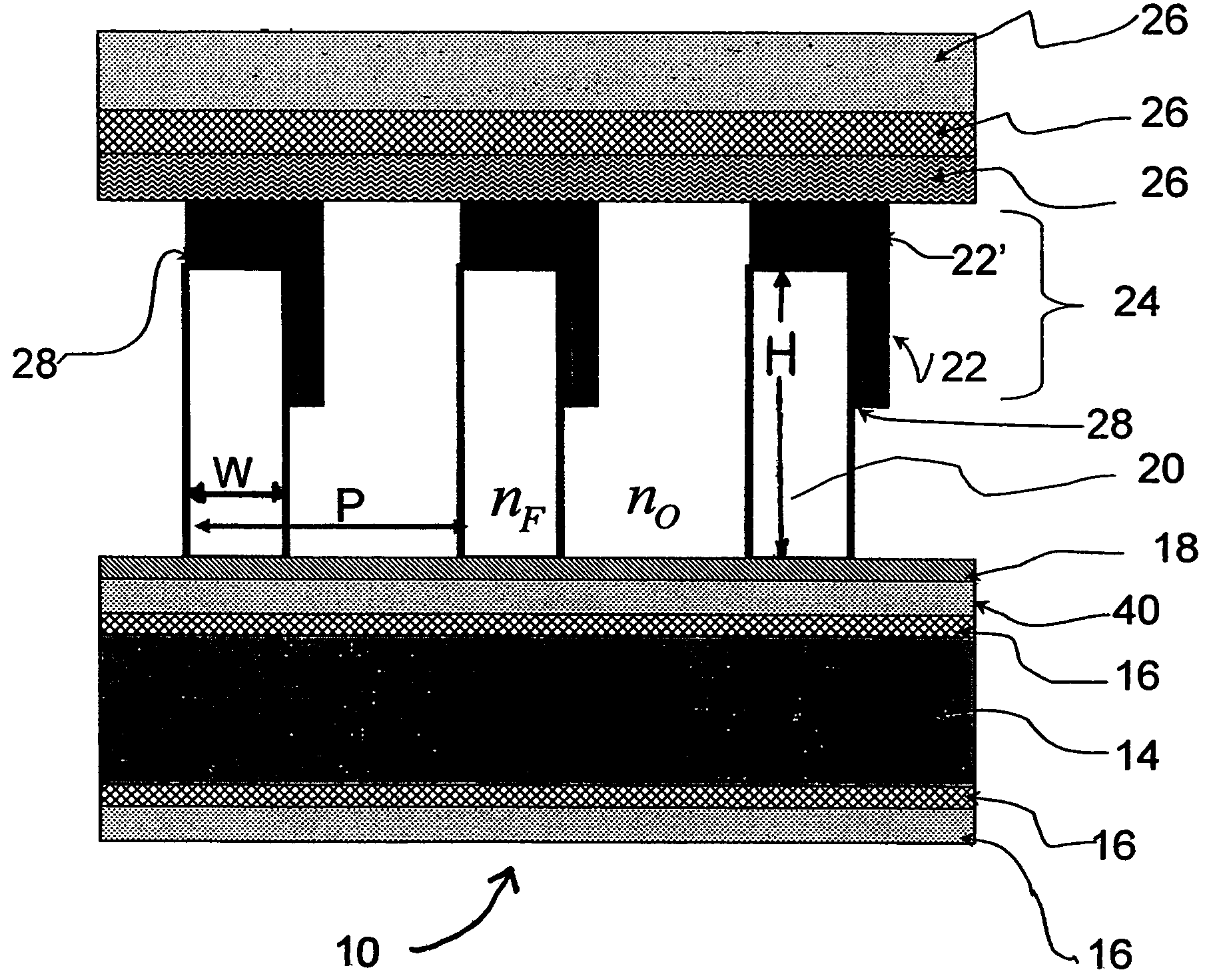
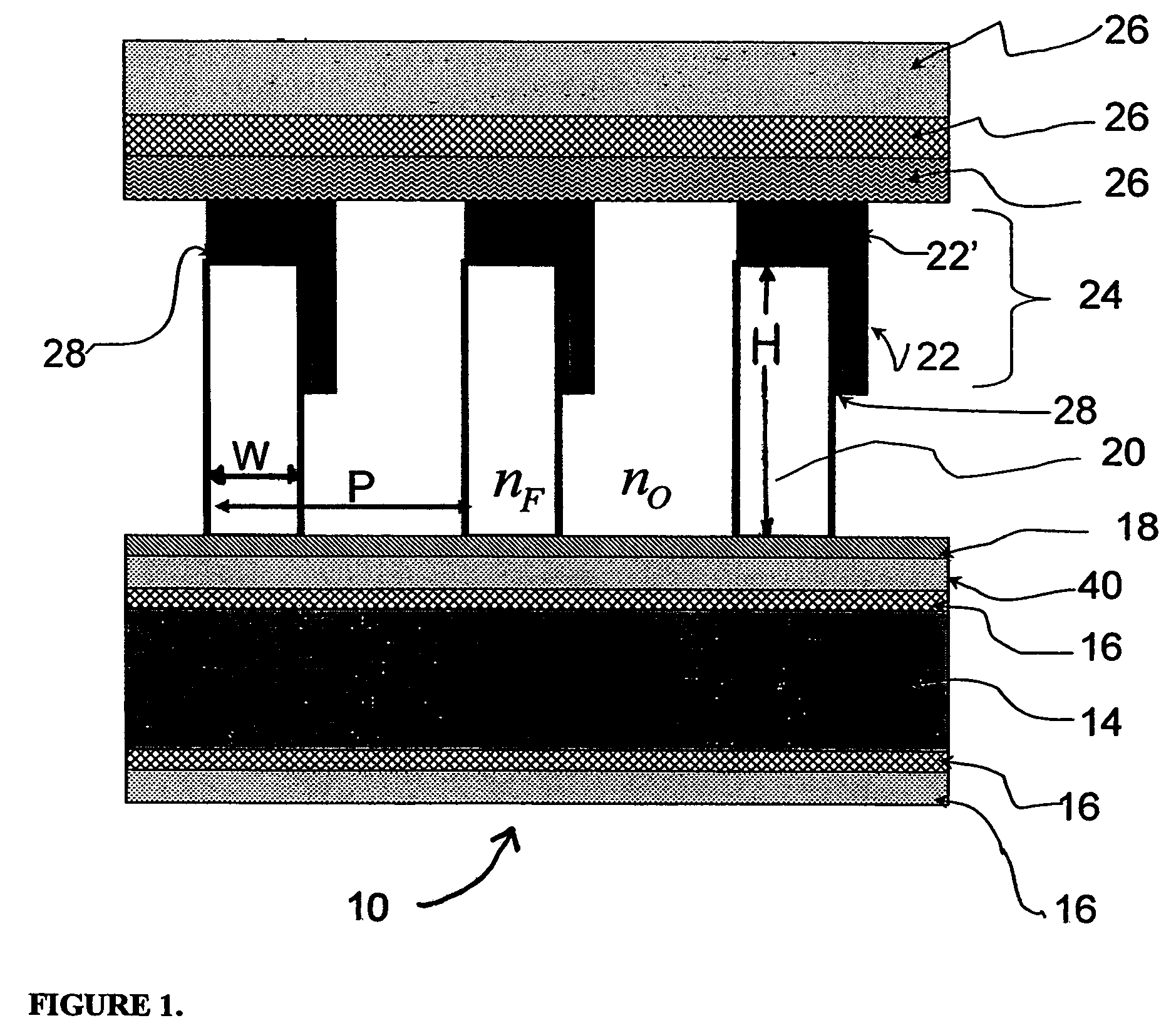
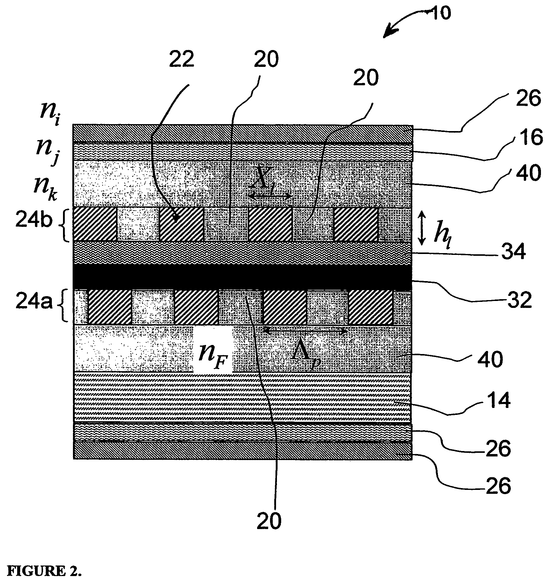
[0025]FIG. 1 shows a schematic diagram illustrating a polarizing beam combiner / beam splitter (“PBC / PBS”) 10. The PBC / PBS 10 may include, for example, a substrate 14 upon which is resident am anti-reflection coating (ARC) 16. Further, a second ARC 16 may be resident upon the substrate 14 below a residual layer 18....


PUM


Abstract

A radiation polarizer, controller, and a method of radiation polarization and beam control, are disclosed. The radiation polarizer includes a substrate, at least one anti-reflection coating layer communicatively coupled to the substrate, at least two nanostructures communicatively coupled to the at least one anti-reflection coating layer, and at least two groove layers, wherein each one of the at least two groove layers is interstitial to a respective one of the at least two nanostructures. The method may include the steps of communicatively coupling at least one anti-reflection coating layer to a substrate, communicatively coupling at least two nanostructures to at least one of the at least one anti-reflection coating layer, providing interstitially to a respective one of the at least two nanostructures at least two groove layers, coupling the at least two groove layers and the at least two nanostructures to provide a pass wavelength in the range of about 250 nm to less than about a microwave wavelength, and allowing for examining of radiation having a wavelength in a range of about 250 nm to less than about a microwave wavelength, and having an electric field orthogonal to the at least two groove layers, by allowing for a passing of the radiation through said coupling of the at least two groove layers and the at least two nanostructures.

Description

CROSS-REFERENCE TO RELATED APPLICATIONS[0001]This application is related to U.S. Patent Applications Ser. No. 60 / 404,746 entitled “Multilayer Structures for Polarization and Beam Control,” filed Aug. 21, 2002, which is hereby incorporated herein as if set forth herein in the entirety.FIELD OF THE INVENTION [0002]The present invention generally relates to methods and systems for broadband polarization beam combining and separation, polarizers, and polarization dependent multiplexing / demultiplexing. More particularly, the present invention relates to nanostructures employed to perform polarization beam combining or separation, polarizers, and polarization dependent multiplexing / demultiplexing.BACKGROUND OF THE INVENTION[0003]A light wave may be formed of electrical field vectors, i.e. peaks and troughs, radiating out in all directions from the direction of propagation of the light wave. A polarizer may be, in essence, a screen that allows only a narrow segment of the vectors to pass, ...

Claims


Application Information

Patent Timeline
IPC IPC(8): G02B27/28G02B5/30G02B5/18
CPCB82Y20/00G02B5/1823G02B5/1861G02B5/3041G02B5/3058
Inventor WANG, JIANDENG, XUEGONGBLONDER, GREGCHEN, ERLI
Owner API TECH
Why Eureka
Try Eureka