Method and apparatus for forming multiple beams

a beam and beam technology, applied in the field of beam forming, can solve the problems of not being able to add more hardware to the circuit board, and the cost of forming a network for each beam,

Inactive Publication Date: 2007-06-05
PHYSIOSONICS
View PDF21 Cites 14 Cited by
  • Summary
  • Abstract
  • Description
  • Claims
  • Application Information

AI Technical Summary

Problems solved by technology

Having a separate beam forming network for each beam is costly in terms of hardware needed, and it does not scale with requirements (it may not be possible to add more hardware to a circuit board).

Method used


Image

  • Method and apparatus for forming multiple beams
  • Method and apparatus for forming multiple beams
  • Method and apparatus for forming multiple beams

Examples


first embodiment

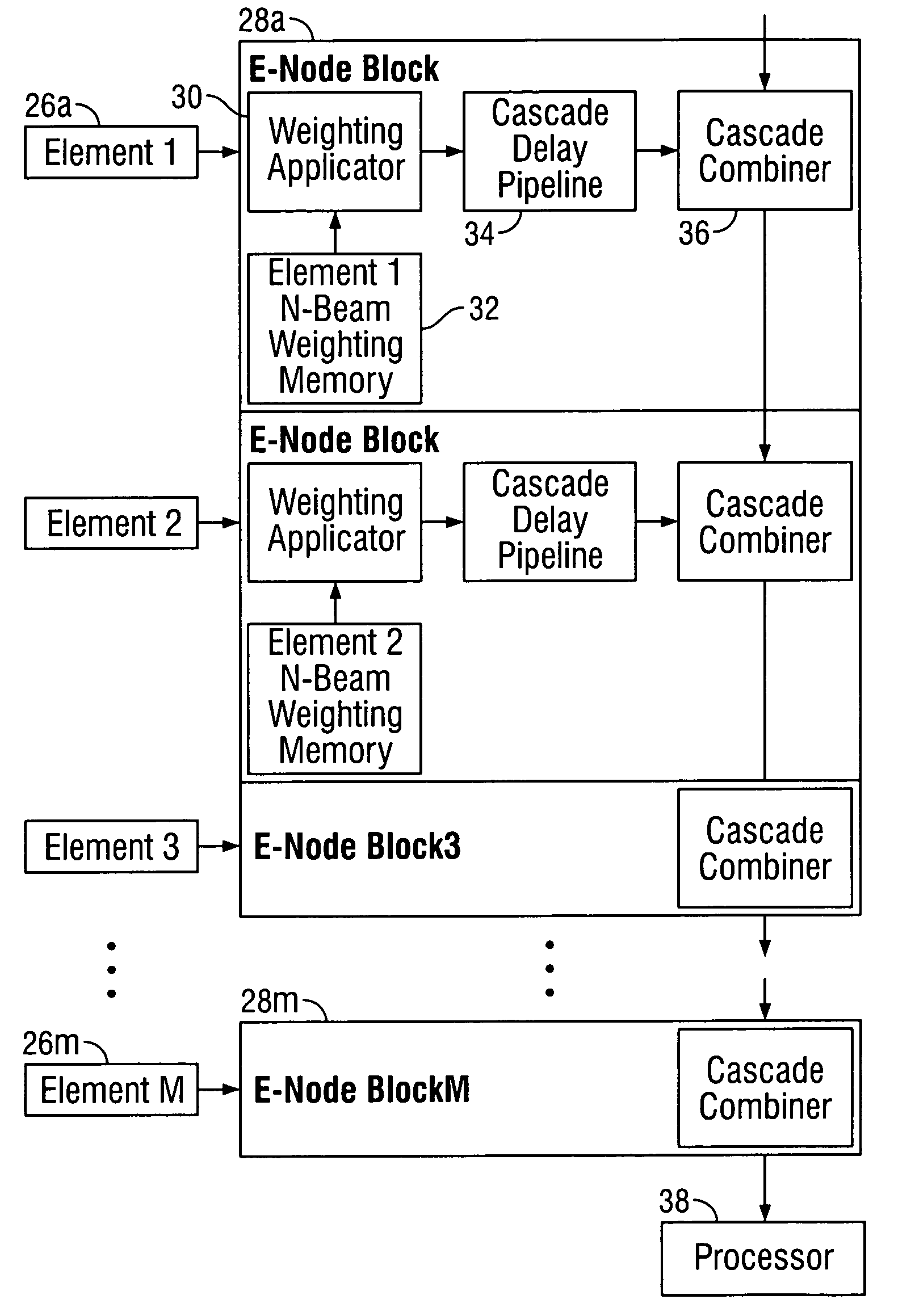
[0030]With regard to FIG. 4, a first embodiment weighting applicator 30 is depicted. In this embodiment, complex phasor multiplication is used to achieve the required phase shift for aligning each received signal sample, e.g., from element 26a. The received sample from element 26a contains a real (in-phase) component I appearing at complex weighting multiplier input 40i, and imaginary (quadrature) component Q appearing at complex weighting multiplier input 40q. The weight loaded from weighting memory 32 has in-phase component Wi appearing at complex weighting multiplier input 42i, and imaginary (quadrature) component Wq appearing at complex weighting multiplier input 42q. Input 40i is fed to multipliers 44a and 44d; input 40q is fed to multipliers 44b and 44c; input 42q is fed to multipliers 44b and 44d, and input 42i is fed to multipliers 44a and 44c. Multiplier 44a produces intermediate result 46a; multiplier 44b produces intermediate result 46b; multiplier 44c produces intermedia...

second embodiment

[0032]With regard to FIG. 5, weighting applicator 30 is depicted. Instead of multiplying complex phasors as in FIG. 4, a delay is used to align components of a beam. The received sample from e.g., element 26a, is fed into element sample input 54 of weighting applicator 30. Sample input 54 passes sequentially through a series of storage registers 56a through 56z (as shown by shifts to the right), whose outputs 58a through 58z are fed to delay line mux (multiplexer) selector 60. Each shift through the storage registers 56a through 56z imparts a certain amount of delay to sample input 54. Storage registers 56a through 56z are clocked by input sample clock input 62 at a rate equal to the input sampling frequency. One of outputs 58a through 58z, which is selected by delay line mux selector 60 via selector input 64, represents the total delay desired to line up a signal sample, e.g. from element 26a, to a desired phase (depending on the beam to be selected, the particular element sampled,...


PUM


Abstract

An apparatus and associated method are disclosed which form a multiple beam forming network using time division multiplexing. Instead of having several parallel sets of beam forming network hardware running at a given sampling clock rate, a simpler, single piece of hardware is run at a faster rate equal to the given sampling clock rate times the number of beams to be formed. Each sample received from each element is time division multiplexed into a bit stream, one for each beam. These time division multiplex element samples are weighted to apply the desired phase shift / time delay per element. Each weighted resultant is delayed in a cascade delay pipeline and then combined with the cascade combiner to form a beam at a given time division instant. This process is repeated for the next set of time division multiplexed samples and weights from each element of the array at a given time to form the next beam. The process is repeated for all beams until the sampling time interval ends.

Description

CROSS-REFERENCE TO RELATED APPLICATION [0001]This application claims the benefit of U.S. Provisional Application Ser. No. 60 / 454,959 filed Mar. 14, 2003.FIELD OF THE INVENTION [0002]The present invention relates to beam forming, and more particularly, to forming multiple beams using time division multiplexing.BACKGROUND OF THE INVENTION [0003]Several techniques exist for locating an object using wave propagation. In the fields of sonar, radar, ultrasound, and telecommunications, transmitting / receiving elements are placed in an array. Some or all of the elements of the array emit pulses of electromagnetic radiation or sound toward a target, and reflections from the target are received at all of the elements. Since the received signals arrive at different times at each element, if the signals are summed at a given time, then some signals will be in phase and some will be out of phase. The summation will be less than the maximum amplitude possible. To receive the maximum amplitude poss...

Claims


Application Information

Patent Timeline
Patent Type & Authority Patents(United States)
IPC IPC(8): A61B8/00H01Q25/00
CPCG01S7/5209G01S15/8909H01Q25/00
Inventor MILLER, CHRISTOPHER X.
Owner PHYSIOSONICS
Why Eureka
Try Eureka