Methods for treating and repairing mitral valve annulus

Inactive Publication Date: 2007-06-12
VALVECURE
View PDF52 Cites 126 Cited by
  • Summary
  • Abstract
  • Description
  • Claims
  • Application Information

AI Technical Summary

Benefits of technology

[0035]The catheter system of the present invention has several significant advantages over known catheters or ablation techniques for repairing an annular organ structure of a heart valve, a valve leaflet, chordae tendinae, papillary muscles, venous

Problems solved by technology

CHF can ultimately lead to end-organ failure, which contributes to death of the patient.
If untreated, CHF may result in severe lifestyle restrictions and ultimately death.
One of the causes of CHF and a very common contributor to the harmful effects of CHF is a leaky mitral heart valve.
Valve replacement using a tissue valve suffers long-term calcification problems.
The current technology for valve repair or valve replacement requires an expensive open-heart surgery that needs a prolonged period of recovery.
A less invasive or catheter-based valve repair technology becomes an unmet clinical challenge.
Many of the defects are associated with dilation of the valve annulus.
This dilatation not only prevents competence of the valve but also results in

Method used


Image

  • Methods for treating and repairing mitral valve annulus
  • Methods for treating and repairing mitral valve annulus
  • Methods for treating and repairing mitral valve annulus

Examples


first embodiment

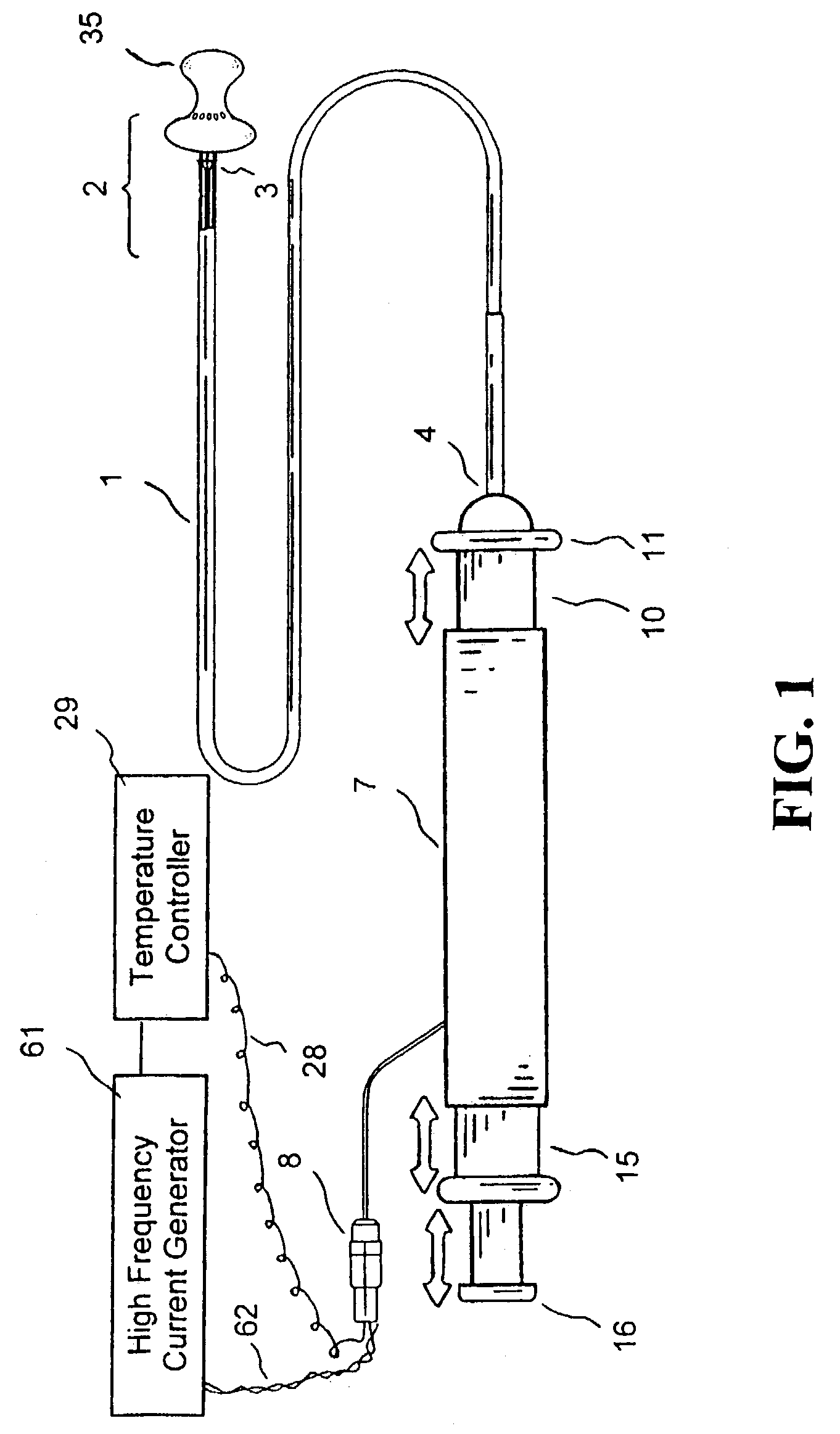
[0061]FIG. 1 shows a catheter system having a flexible tissue-contactor member 35 and electrode element means at its distal tip section 2 constructed in accordance with the principles of the present invention. As disclosed in the current invention, the tissue-contactor member 35 is generally configured to be retracted within one of the at least one lumen 14 during catheter insertion into and removal from the patient.

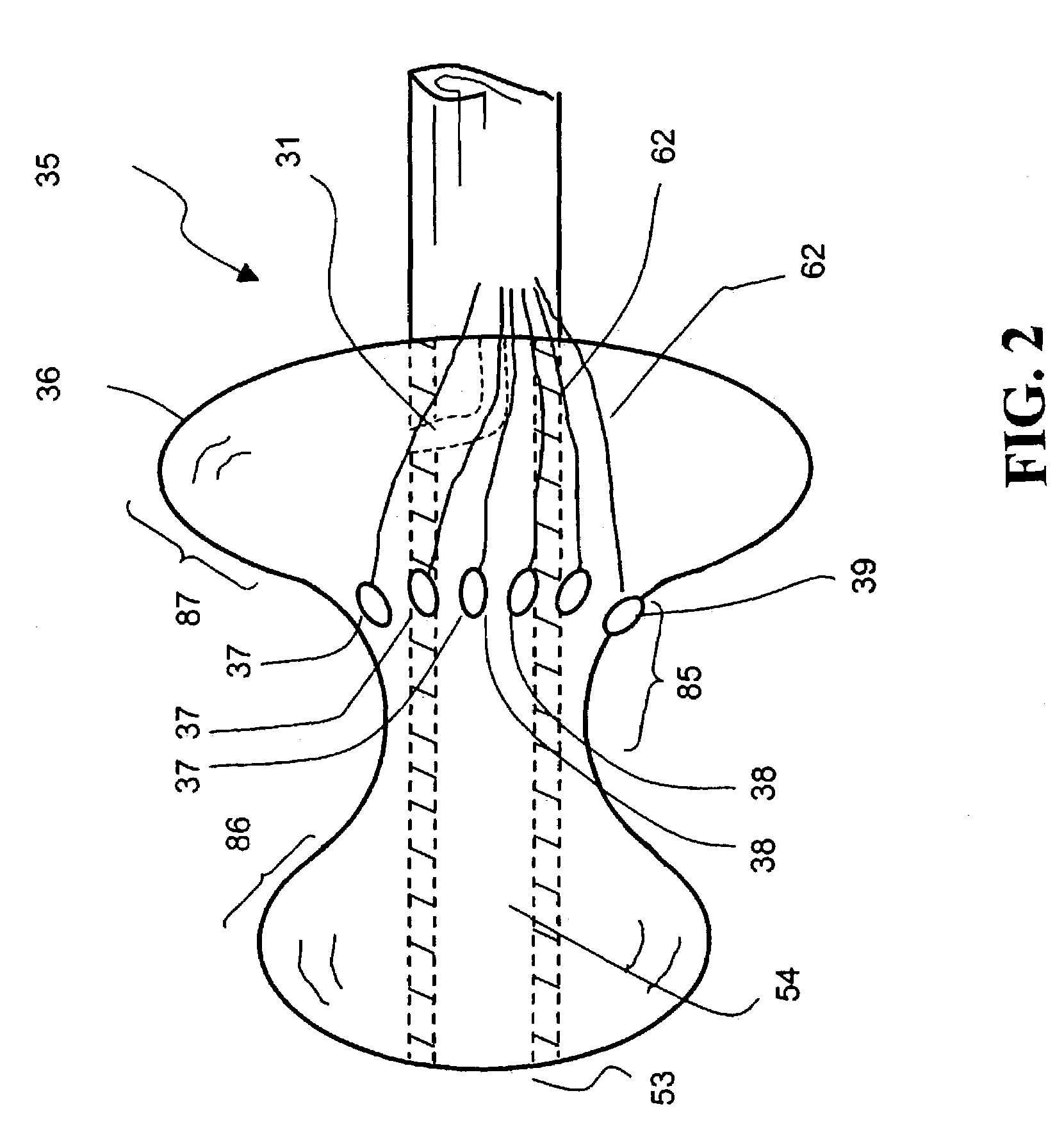
[0062]FIG. 2 shows a detailed cross-sectional view of the distal tip section 2 of the catheter system according to FIG. 1, comprising a deployed tissue-contactor member 35 for treating the tissue of an annular organ structure. In a first preferred embodiment, the tissue-contactor member 35 may comprise a “double-mound” shaped balloon made of flexible expandable biocompatible material selected from a group consisting of silicone, latex, polyurethane, fluoro-elastomer, polypropylene, polyethylene, polyethylene terephthalate, nylon, and a combination thereof. The “double-mo...

second embodiment

[0068]FIG. 6 shows a third step of deploying a tissue-contactor member 45 of the catheter system in FIG. 3 for treating the tissue of an annular organ structure, comprising deployment of the electrode element means 48. The electrode element means 48 may comprise a plurality of basket members that are expandable radially outwardly with a conductive surface 43 on each basket member facing outwardly. Other surface areas of the basket members away from the conductive surface 43 are insulated and not conductive. As disclosed and well known to a skilled artisan, an electrical conductor means 62 for transmitting high frequency current from a high frequency current generator 61 to the electrode elements 48 is provided.

[0069]In a preferred embodiment, a method for operating a catheter system of the present invention for repairing a valvular annulus, the method may comprise: (a) percutaneously introducing the catheter system through a blood vessel to a site of the valvular annulus or introdu...

third embodiment

[0070]FIG. 7 shows a catheter system having a deployed flexible tissue-contactor member 95 and electrode element means at its distal tip section constructed in accordance with the principles of the present invention. The acorn-shaped tissue-contactor member 95 is to compressively sandwich a target annulus from two sides of the annulus at about 90 degrees to each other.

[0071]FIG. 8 shows a detailed cross-sectional view of the distal tip section 2 of the catheter system 1 according to the third embodiment in FIG. 7, comprising a deployed tissue-contactor member 95 for treating the tissue of an annular organ structure. In an example of mitral annulus treatment for illustration purposes, the first balloon 91 is intended to lie on top of the annulus while the flexible electrode elements 96 made of conductive elastomer material are intended to provide sufficient therapeutic energy for treating the annulus. The second balloon 59 is intended to lie against the inner wall of the annulus so t...


PUM


Abstract

A catheter system and methods for repairing a valvular annulus or an annular organ structure of a patient comprising intimately contacting the annular organ structure by a tissue-contactor member having energy-delivering elements, and delivering tissue-shrinkable energy at the annular organ structure through the elements, wherein the tissue-shrinkable energy is applied at a distance wirelessly from the elements sufficient to shrink and tighten the organ structure.

Description

CROSS REFERENCE TO RELATED APPLICATION[0001]This application is a continuation-in-part of application Ser. No. 10 / 292,824, filed Nov. 12, 2002, now abandoned, which is a continuation-in-part of application Ser. No. 10 / 101,230, filed Mar. 19, 2002, now U.S. Pat. No. 6,485,489, which is a continuation-in-part of application Ser. No. 10 / 083,264, filed Oct. 22, 2001, now abandoned, which is a continuation-in-part of application Ser. No. 09 / 410,902 filed Oct. 2, 1999, now U.S. Pat. No. 6,306,133, all of which are incorporated by reference herein in their entireties. This application also claims the priority benefits of a provisional application Ser. No. 60 / 383,725 filed May 28, 2002.FIELD OF THE INVENTION[0002]The present invention generally relates to a system and methods for applying therapeutic energy to a patient for medical purposes such as reducing and / or shrinking a tissue mass. More particularly, the invention relates to an ablation catheter or probe system that selectively conta...

Claims


Application Information

Patent Timeline
IPC IPC(8): A61N1/05A61B18/12
CPCA61B18/1492A61B2018/00214A61B2018/00369A61B2018/00898A61B2018/1435
Inventor WITZEL, THOMASHAUCK, WALLACE NOSTH, JOHN A.TU, HOSHENG
Owner VALVECURE
Why Eureka
Try Eureka