
High speed tool steel

a tool steel, high-speed technology, applied in the field of high-speed tool steel, can solve the problems of low carbon content of steel, poor toughness and mechanical properties of conventional tool steels, and occurrence of heat cracks in tool products, so as to improve the strength of the matrix, improve the toughness of the tool steel, and improve the hardness

Active Publication Date: 2007-06-12
HITACHI METALS LTD
View PDF5 Cites 2 Cited by
  • Summary
  • Abstract
  • Description
  • Claims
  • Application Information

AI Technical Summary

Benefits of technology

[0024]Hereunder, first of all, description will be given to advantageous effects of each of elements in chemical composition of the tool steel of the present invention as well as reasons for restricting the amount of each of the elements of the tool steel.
[0025]In the tool steel, carbon or C is combined with the other elements such as Cr, W, Mo, V, Nb and the like to form two types of primary carbides both high in hardness. Consequently, addition of an appropriate amount of C in composition to the tool steel is effective in improving the tool steel in wear resistance.
[0026]Further, since the element C is partially solid-soluble in the matrix of the tool steel, it may contribute to improvement of the matrix in strength. However, when the C content in composition of the tool steel is excessively large, segregation of the carbides is enhanced. On the other hand, when the tool steel is poor in the C content in composition, such tool steel fails to obtain a necessary hardness. For these reasons, in the tool steel of the present invention, the C content is limited to an amount of ranging from 0.4 mass % to 0.9 mass %.
[0027]As for Si, since it is necessary for the tool steel to contain the element Si as a deoxidizer, the tool steel contains the element Si as one of its inevitable impurities. However, when the Si content in the tool steel is in excess of 1.0 mass %, the tool steel suffers from excessive hardness even after completion of annealing of the steel. Such excessive hardness decreases the cold-working properties of the tool steel. For these reasons, in the tool steel of the invention, the Si content is limited to an amount of up to 1.0 mass %. In addition, the element Si is also recognized to be effective in transforming the primary carbides of stick-shaped M2C type into finely-divided spheroidal carbides. For this reason too, it is preferable to limit the Si content to an amount of equal to or less than 0.1 mass % in the tool steel of the present invention.
[0028]As for Mn, addition of the element Mn to the tool steel is effective in improving the tool steel in hardenability. However, when the Mn content is too large, the A1 transformation point of the tool steel is excessively lowered, which means that the hardness of such tool steel is excessively increased even after completion of annealing. Therefore, this results in the tool steel poor in machinability. For these reasons, in the tool steel of the present invention, the Mn content is limited to an amount of up to 1.0 mass %. Incidentally, in order to improve the tool steel in hardenability, it is preferable to add the element Mn to the tool steel by an amount of at least 0.1 mass %.
[0029]As for Cr, the element Cr combines with C to form the carbides in the tool steel to improve the steel in both wear resistance and hardenability. However, when the Cr content is too large, stripe- or streak-like segregation of the carbides increases in the matrix of the tool steel. This deteriorates the tool steel in cold-rolling or -working properties. On the other hand, when the Cr content is too small, any effective improvement can't be obtained in the tool steel. For these reasons, in the tool steel of the present invention, the Cr content is limited to an amount of ranging from 4 mass % to 6 mass %.

Problems solved by technology

However, these conventional types of tool steels are still poor in toughness and like mechanical properties.
This often leads to breakage and occurrence of heat cracks of a tool product made of the conventional types of tool steels in use.
More particularly, in case of the former steel (i.e., hot working tool steel), this type of steel is low in carbon content and therefore low in cold strength.
Due to this, the former steel often suffers from its poor resistance to fatigue and poor wear resistance together with its breakage in use.
However, such large-sized ingot often varies in composition of its carbides.
However, the product made of the tool steel is still poor in toughness in use.

Method used


Image

  • High speed tool steel
  • High speed tool steel
  • High speed tool steel

Examples


example

[0071]Re: The Research for Finding Out the Root Causes of the Premature Fractures:

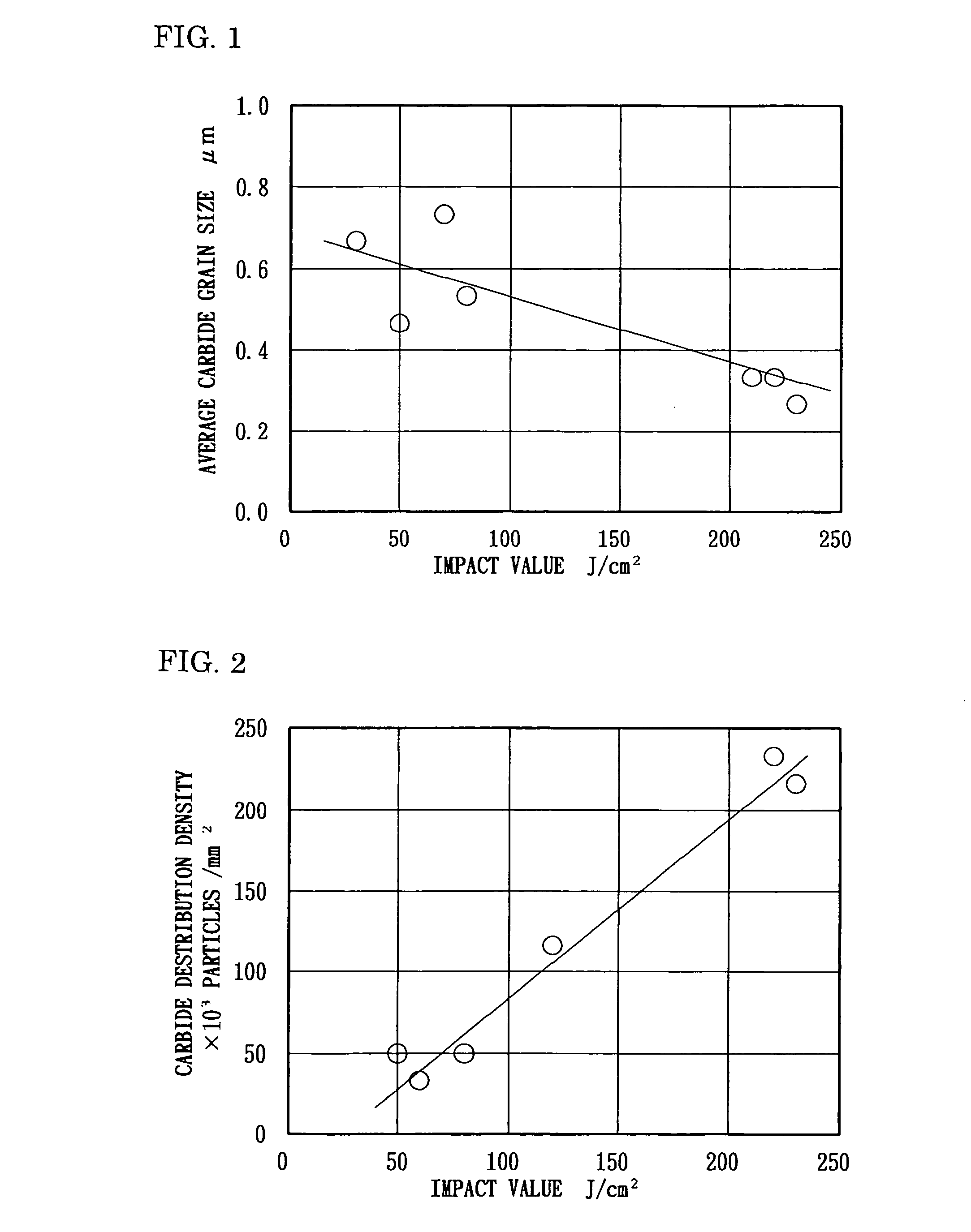
[0072]In order to diagnose the premature fractures of a high speed tool steel, the inventors have researched the relationship between the impact value of the tool steel and each of: the average grain size of the precipitated carbides in the high speed tool steel; and, the distribution density of fine particles of the carbides in the tool steel. Specimens were obtained from the tool steel. Each of these specimens was first quenche data temperature of 1140° C., and then subjected to a tempering process at a temperature of 560° C. After that, the thus prepared specimen was subjected to a so-called “C-notched Charpy impact test” to determine the impact value of the tool steel. In this “C-notched Charpy impact test”, the specimen which was equal, in shape and dimension, to a “10RC notched Charpy test bar” shown in FIG. 11 was used. The test results of this “C-notched Charpy impact test” are shown in FIGS. 1...


PUM

PropertyMeasurementUnit
grain sizeaaaaaaaaaa
temperatureaaaaaaaaaa

Abstract

A high speed tool steel, which is high in impact value and free from variations in tool performance, comprising, by mass %, of: 0.4≦C≧0.9; Si≦1.0; Mn≦1.0; 4≦Cr≧6; 1.5–6 in total of either or both of W and Mo in the form of (½W+Mo) wherein W≦3; 0.5–3 in total of either or both of V and Nb in the form of (V+Nb); wherein carbides dispersed in the matrix of the tool steel have an average grain size of ≦0.5 μm and a dispersion density of particles of the carbides is of ≧80×103 particles / mm2.

Description

BACKGROUND OF THE INVENTION[0001]1. Field of the Invention[0002]The present invention relates to a high speed tool steel excellent in cold strength, wear resistance and in hardenability and also to a method for manufacturing such high speed tool steel. More particularly, the present invention relates to a high speed tool steel particularly excellent in hot strength and in toughness with a minimum variation in tool performance when used as a material for: a metallic mold used for forming plastics; and, a swaging tool, for example such as a press forming die, a press forming punch and like tools.[0003]2. Description of the Related Art[0004]Heretofore, widely used as materials in production of: a tool such as a press forming punch used in hot precision press working; and, a metallic mold used for forming plastics, are those excellent in hot strength or toughness, for example such as: a hot working tool steel of the type “AISI H19”; and, a high speed tool steel of the type “AISI M2”. Ho...

Claims


Application Information

Patent Timeline
Patent Type & Authority Patents(United States)
IPC IPC(8): C22C38/22C22C38/24C22C38/26C22C38/44C22C38/30C21D6/00C22C38/00C22C38/52
CPCC21D6/002C22C38/02C22C38/04C22C38/22C22C38/24C22C38/26C22C38/44C22C38/46C22C38/48C22C38/52B25B23/065B25B13/06B25B23/02
Inventor FUKUMOTO, SHIHOINOUE, KEIJI
Owner HITACHI METALS LTD
Learn More