Printed wiring board and its manufacturing method
a printing method and wiring board technology, applied in the direction of printed element electric connection formation, superimposed coating process, liquid/solution decomposition chemical coating, etc., can solve the problems of low elongation and high tensile strength characteristics, poor ductility of thick plated copper layer formed by electroless plating, and tendency to develop cracks and other flaws. , to achieve the effect of low equipment cost and good crystallinity
- Summary
- Abstract
- Description
- Claims
- Application Information
AI Technical Summary
Benefits of technology
Problems solved by technology
Method used
Image
Examples
example 1
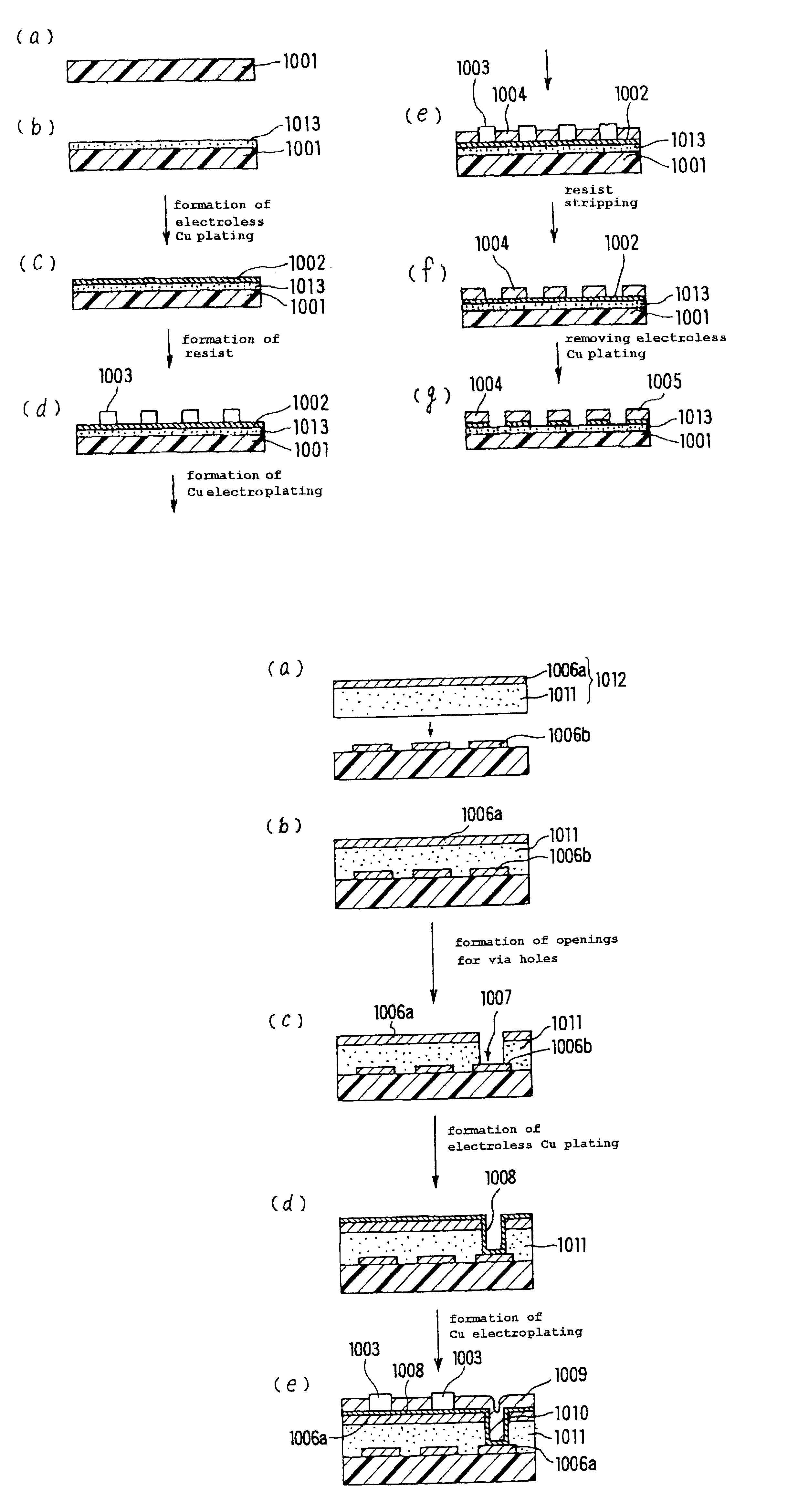
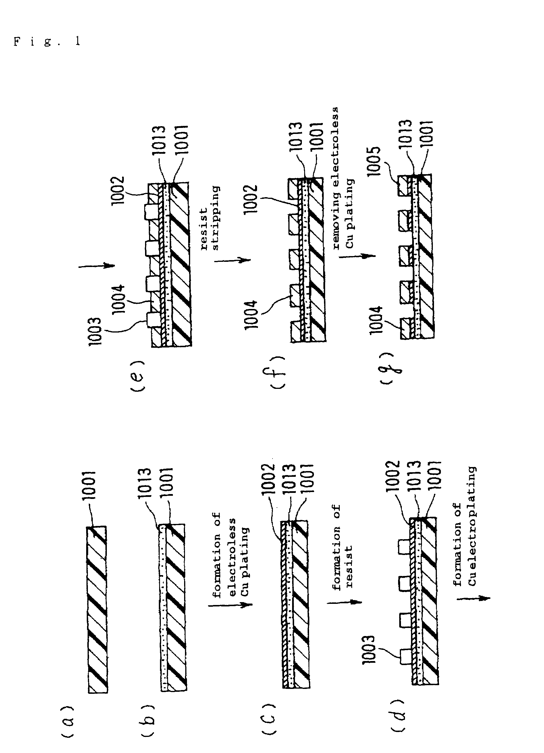
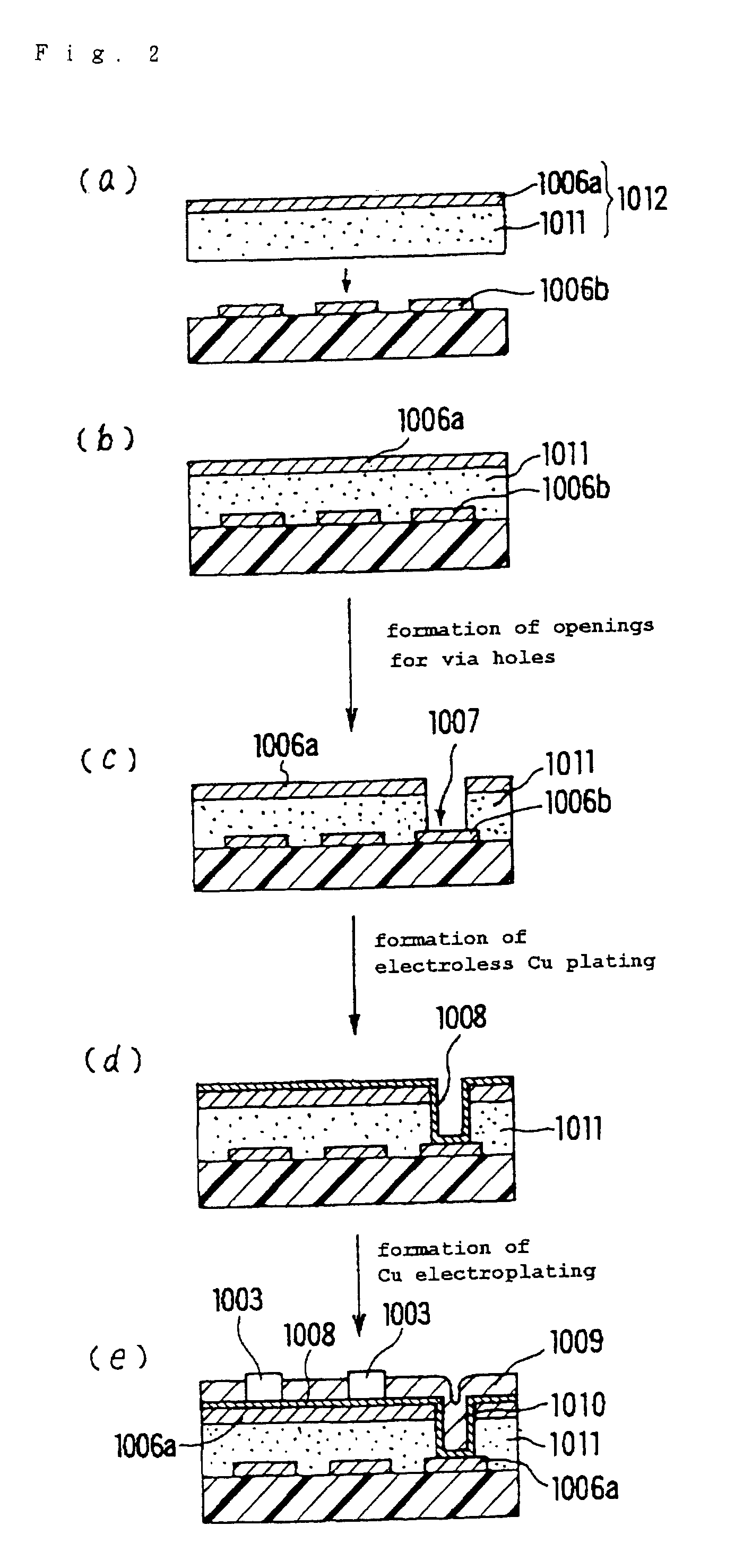
[0437]FIG. 1 (a) to (g) show an exemplary process for fabricating the conductor circuit of the printed circuit board according to the invention and FIG. 2 (a) to (e) show an exemplary process for manufacturing a multilayer printed circuit board in accordance with the invention.
[0438]In constructing the conductor circuit on a printed circuit board, an insulating substrate 1001 of glass cloth-epoxy resin or BT material was used as the insulating sheet as shown in FIG. 1 (a).
[0439]Then, 35 weight parts of acrylate (25 wt. %) of cresol novolac epoxy resin (Nippon Kayaku; mol. wt. 2500), 3.15 weight parts of photosensitive monomer (To a Gosei Co.; trade mark, Aronix M315), 0.5 weight part of antifoam (Sun Nopco, S-65), 3.6 weight parts of N-methylpyrrolidone (NMP), 12 weight parts of polyethersulfone (PES), and epoxy resin powders (Sanyo Kasei; Polymerpol; 1.0 μm of average particle diameter, 7.2 wt. Parts, and 0.5 μm of average particle diameter, 3.09 wt. parts) were mixed together, and...
example 2
[0476]The following is an example of application of this invention to the manufacture of a CMOS IC chip.
[0477]An IC wafer was fabricated by the well-known MOS wafer production technology, for example by the process described in LSI Process Engineering, pp. 22 to 23 [Published by Ohm-sha, K. K., Jun. 20, 1987] [FIG. 10 (a)].
[0478]The whole surface of a substrate was subjected to Cu sputtering to provide a Cu layer 1014 in a thickness of 0.6 μm (FIG. 10 (b)). Cu sputtering can be carried out using a vacuum sputtering equipment (Tokuda Seisakusho; CFS-8EP).
[0479]Then, using a spin coater, a negative photoresist (Tokyo Auka Kogyo; OMR83) was coated on the Cu layer 1014, followed by drying. Thereafter, prebaking, exposure, development and postbaking were performed in succession to provide a plating resist 1015 (4 μm thick, L / S=20 / 20 μm). Then, the sheet was immersed in 10% aqueous solution of sulfuric acid for surface activation and constant-voltage pulse copper electroplating was perfor...
example 3
A. Preparation of a Resin Composition for Forming Roughened Surface
[0481]Mixing 34 weight parts of the resin solution dissolving 25% acrylate of a cresol novolac epoxy resin (Nippon Kayaku, mol. wt. 2500) in diethylene glycol dimethyl ether (DMDG), and, 2 weight parts of imidazole curing agent (Shikoku Kasei; 2E4MZ-CN), 4 weight parts of the photosensitive monomer caprolactone-modified tris (acryloxylethyl) isocyanurate (To a Gosei; trade mark, Aronix M325), 2 weight parts of the photopolymerization initiator benzophenone (Kanto Chemical), 0.2 weight part of the photosensitizer Michler's ketone (Kanto Chemical), 10 weight parts of photosensitive monomer (Nippon Kayaku; KAYAMER PM-21), and epoxy resin powders (Sanyo Kasei, trade mark, Polymerpole; average particle diameter 1.0 μm, 15 weight parts and average particle diameter 0.5 μm, 10 weight parts), and with addition of 30.0 weight parts of N-methylpyrrolidone (NMP), the mixture was adjusted to a viscosity of 7 Pa·s using a homodis...
PUM
 Abstract
Description
Claims
Application Information
 - R&D
- Intellectual Property
- Life Sciences
- Materials
- Tech Scout
- Unparalleled Data Quality
- Higher Quality Content
- 60% Fewer Hallucinations
Browse by: Latest US Patents, China's latest patents, Technical Efficacy Thesaurus, Application Domain, Technology Topic, Popular Technical Reports.
© 2025 PatSnap. All rights reserved.Legal|Privacy policy|Modern Slavery Act Transparency Statement|Sitemap|About US| Contact US: help@patsnap.com


