Power supply system

a power supply system and power supply technology, applied in the direction of electric variable regulation, process and machine control, instruments, etc., can solve the problems of insufficient compatibility of ac adapters, and flood of ac adapters in the house, so as to save space

Inactive Publication Date: 2007-06-19
SHARP KK
View PDF19 Cites 269 Cited by
  • Summary
  • Abstract
  • Description
  • Claims
  • Application Information

AI Technical Summary

Benefits of technology

[0016]In light of the above problems, it is an object of to provide a power supply system capable of not only supplying power to different types of electronic equipment by using a single power transmission apparatus, but also saving space and performing payment for public service and charges.
[0021]According to still another aspect of the technology, the power transmission apparatus is incorporated in a utensil. Therefore, it is possible to use a single type of power transmission apparatus for feeding power to different types of power reception equipment, thereby making it possible to achieve a power supply system contributing to space saving.

Problems solved by technology

This means that there is no compatibility among AC adapters.
Especially, in the case of the portable telephone, dedicated AC adapters are used for respective portable telephones which are different in model or make, thereby providing no compatibility among these AC adapters, only being resulted in inconvenience.
Since there is no compatibility among AC adapters, a problem has arisen that a house is flooded with many AC adapters.
In a case where many adapters are present in a house, another problem has arisen that the AC adapters and cords used for connecting the AC adapters to the commercial power supply become impediments to movement of family members.
In a case where equipment is installed on a shelf, such as a personal computer rack, relocating the equipment involves both the equipment and an AC adapter thereof as a set, only resulting in cumbersomeness.
An AC adapter specially designed for corresponding electronic equipment is necessary to be carried by a person who carries the electronic equipment in a public facility at a destination of travel or in transit, which has greatly devalued portability of the mobile electronic equipment.
When an automobile is used for traveling, a charging adapter is attached to a dashboard, a console box, or the like to thereby charge a portable telephone, whereas in such a case, the adapter and a cord thereof become obstacles during driving, and a case arises where a view field of a driver is partly blocked.
However, only one designated type of electronic equipment can be charged by the non-contact charger with a problem that the non-contact charger cannot charge plural types of electronic equipment.
In such situations, the cashier or the front desk is crowded, causing a problem of disabling a smooth payment.
In a case where a train ticket is purchased from an automatic ticket dispenser, it is necessary to find out a fare to a destination in a fare schedule or the like and then purchase the ticket, which has been problematically cumbersome.
In addition, another annoyance accompanies when the ticket is actually purchased, small change has to be carried.
On the other hand, there is a payment method already available in which a prepaid card is purchased in advance, and the prepaid card is put through an automatic ticket dispenser installed at a ticket gate in a station, and thereby a charge required for a boarding distance is subtracted from a recorded balance on the prepaid card, whereas a problem has remained unsolved that such a prepaid card is not standardized among railway companies.

Method used


Image

  • Power supply system
  • Power supply system
  • Power supply system

Examples


Embodiment Construction

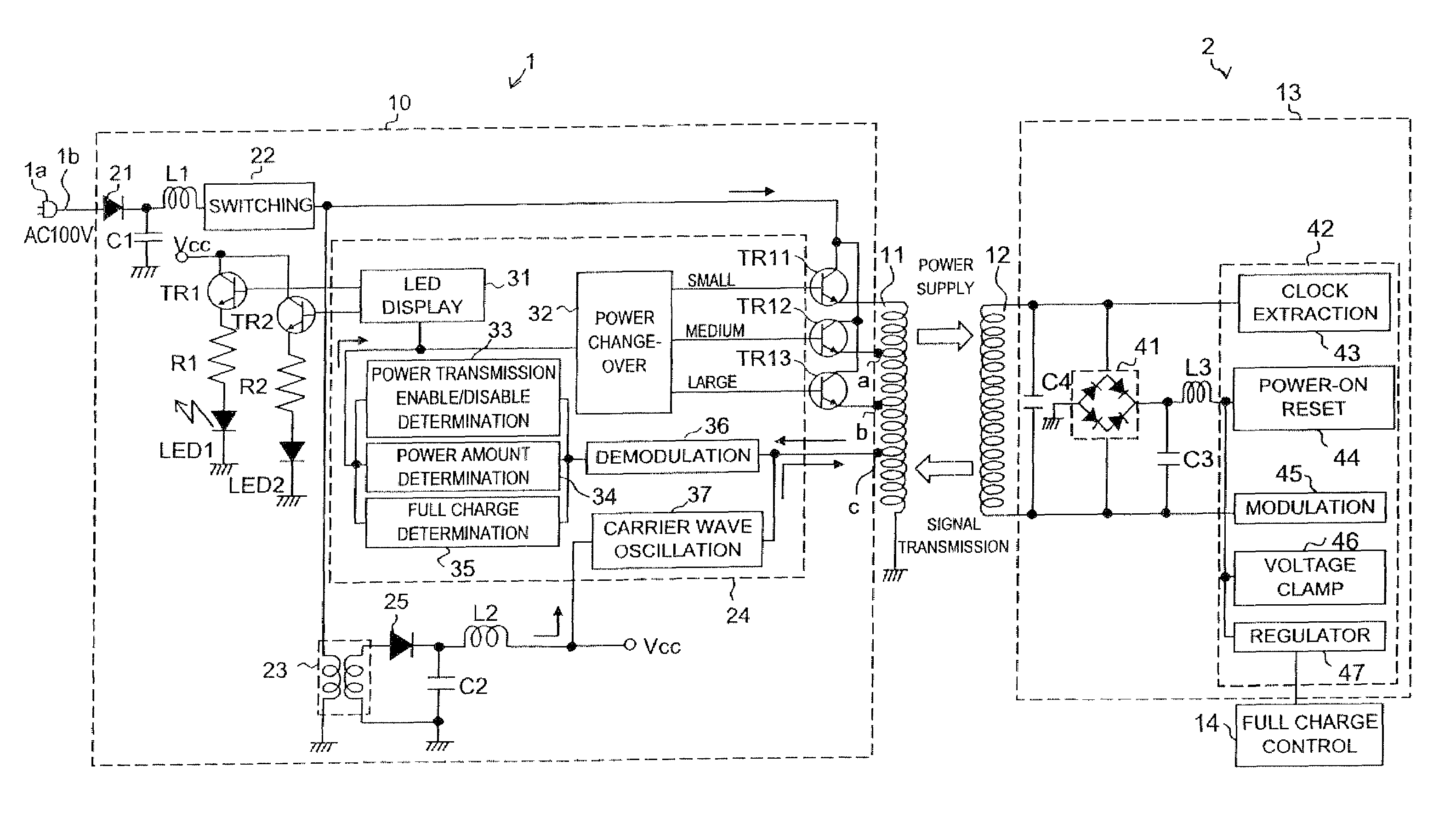
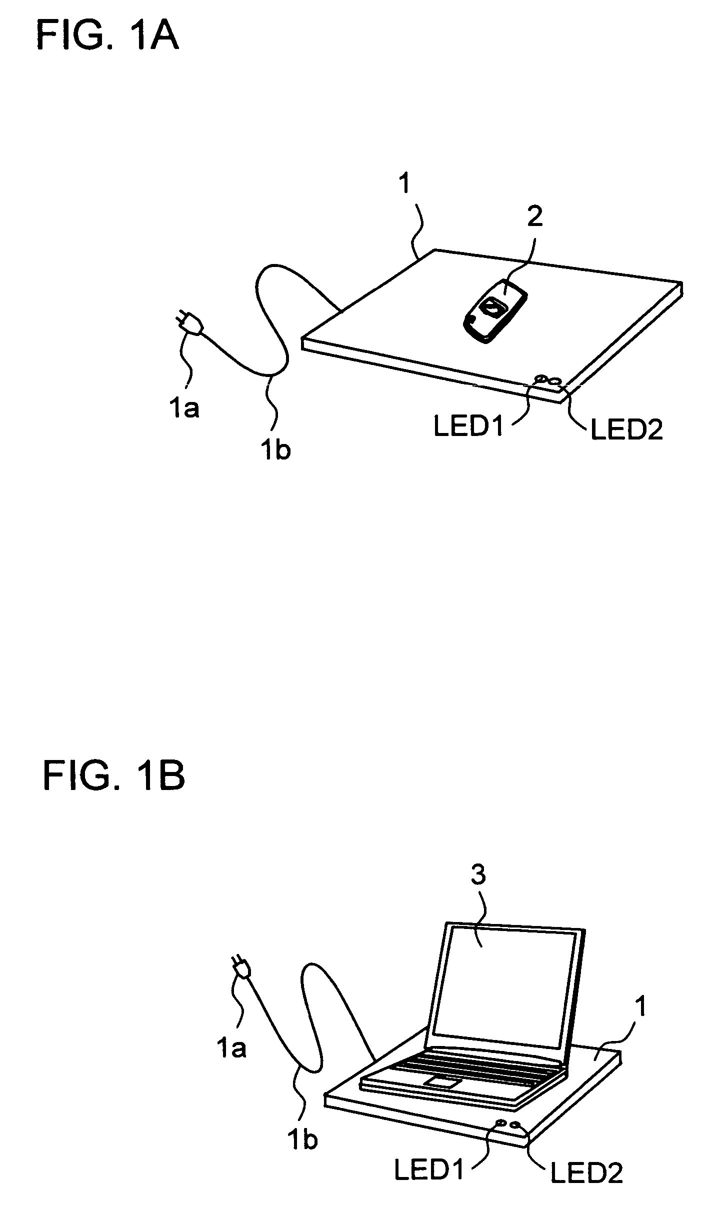
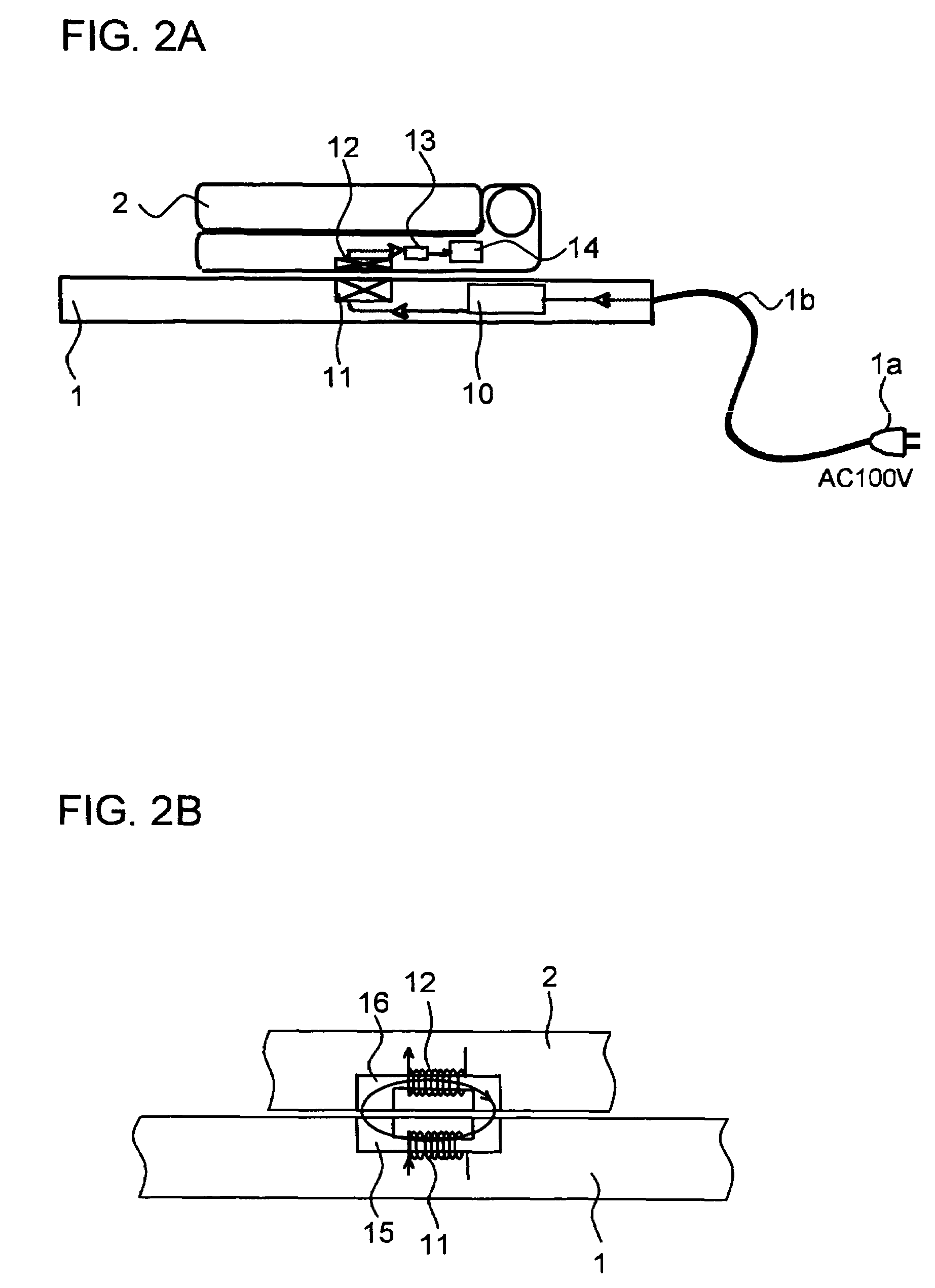
[0062]Description will be given of an embodiment of the present invention below with reference to the accompanying drawings. FIGS. 1A and 1B are views showing outer appearances of power supply systems embodying the present invention. In FIGS. 1A and 1B, a numerical symbol 1 indicates a power transmission apparatus for supplying power. FIG. 1A shows a case where power reception equipment is a portable telephone 2, and FIG. 1B shows a case where the power reception equipment is a notebook PC 3. The power transmission apparatus 1 is equipped with an AC plug 1a and a cord 1b. The AC plug 1a is inserted into a socket provided on a wall surface or the like to thereby feed a commercial power supply (AC 100 V) to the power transmission apparatus 1 through the cord 1b. The power transmission apparatus 1 converts the supplied AC 100 V to a DC voltage, thereafter, the DC voltage is subjected to switching and supplied to a battery of the portable telephone 2 or the notebook PC 3, which is power...


PUM

PropertyMeasurementUnit
DC voltageaaaaaaaaaa
poweraaaaaaaaaa

Abstract

A power supply system is provided, having: a primary side coil; a power transmission apparatus having a primary side circuit for feeding a pulse voltage resulted from switching a DC voltage which is obtained by rectifying and smoothing a commercial power supply to the primary side coil; a secondary side coil magnetically coupled to the primary side coil; and power reception equipment having a secondary side circuit for rectifying and smoothing voltage induced across the secondary side coil, wherein there is provided a power adjusting section for adjusting a level of power to be transmitted according to power required by the power reception equipment. The power adjusting section has, in the primary side circuit, a carrier wave oscillation circuit for supplying a carrier wave to the primary side coil, a demodulation circuit for demodulating a modulated signal transmitted from the secondary circuit and received by the primary side coil, and a power change-over section for selecting a level of power to be transmitted according to an information signal from the power reception equipment and demodulated by the demodulation circuit. The power adjusting section has, in the secondary side circuit, a modulation circuit for modulating the carrier wave fed from the carrier wave oscillation circuit and received by the secondary side coil with the information signal from the power reception equipment and transmitting the modulated signal.

Description

[0001]This non-provisional application claims priorities under 35 U.S.C. §119(a) on Patent Application No. 2003-340631 filed in Japan on Sep. 30, 2003, Patent Application No. 2003-340772 filed in Japan on Sep. 30, 2003, and Patent Application No. 2003-341350 filed in Japan on Sep. 30, 2003, the entire contents of which are hereby incorporated by reference.TECHNICAL BACKGROUND[0002]1. Technical Field[0003]The present invention relates to a power supply system that supplies power to electronic equipment and, more particularly, to a power supply system that supplies power to mobile electronic equipment such as portable telephones, notebook personal computers, a digital cameras, and electronic toys.[0004]2. Description of the Prior Art[0005]In FIGS. 27 to 29, there are shown examples of a conventional power supply system that supplies power to mobile electronic equipment. FIG. 27 is a view showing an outer appearance of a conventional power supply system performing power supply to a por...

Claims


Application Information

Patent Timeline
Patent Type & Authority Patents(United States)
IPC IPC(8): H01F17/00H02M3/335G06F1/26H02J5/00H02J7/00H02J7/02
CPCG06F1/26H02J5/005H02J7/0068H02J7/025H02J50/80H02J50/10H02J7/0049H02J50/90H02J50/40H02J50/60
Inventor NAKAMURA, JUNICHIKAWAMURA, MASAHIROOKADA, YUTAKAMORIMOTO, TAKESHI
Owner SHARP KK
Why Eureka
Try Eureka