Spiral-action damper

a damper and spiral action technology, applied in the direction of shock absorbers, furniture parts, wing accessories, etc., can solve the problem of relatively high price of the damper, and achieve the effect of good braking

Inactive Publication Date: 2007-06-26
ARTURO SALICE
View PDF18 Cites 22 Cited by
  • Summary
  • Abstract
  • Description
  • Claims
  • Application Information

AI Technical Summary

Benefits of technology

[0004]It is thus the object of the invention to create an economically producible damping device of the type mentioned in the introduction, which damping device provides good braking effect even at a short stroke of the plunger or piston.

Problems solved by technology

In known devices of this type, the damping devices which are used for damping or decelerating the furniture parts are impinged upon along only a relatively small path in the closing region of the movable furniture parts so that they are only able to provide a correspondingly modest damping or deceleration action.
Because of the necessary two-stage gear means, these damping devices are relatively expensive.

Method used


Image

  • Spiral-action damper
  • Spiral-action damper
  • Spiral-action damper

Examples


Embodiment Construction

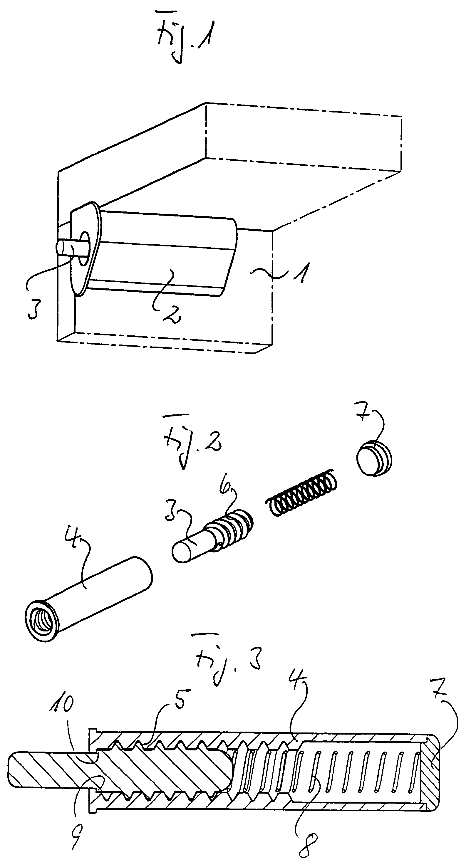
[0039]FIG. 1 shows the upper left corner of a cupboard. At the inside of a sidewall 1 in an adaptor housing 2, which is attached to the side wall, a damping device is held whose plunger 3 protrudes beyond the face of the side wall 1 such that the impact of a door hitting this damping device is dampened.

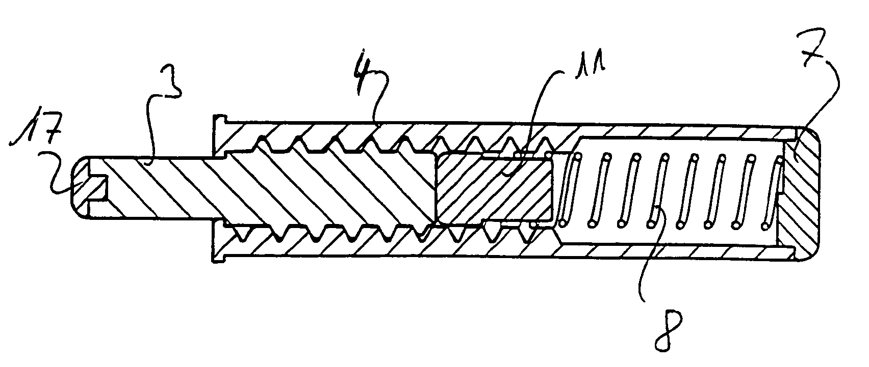
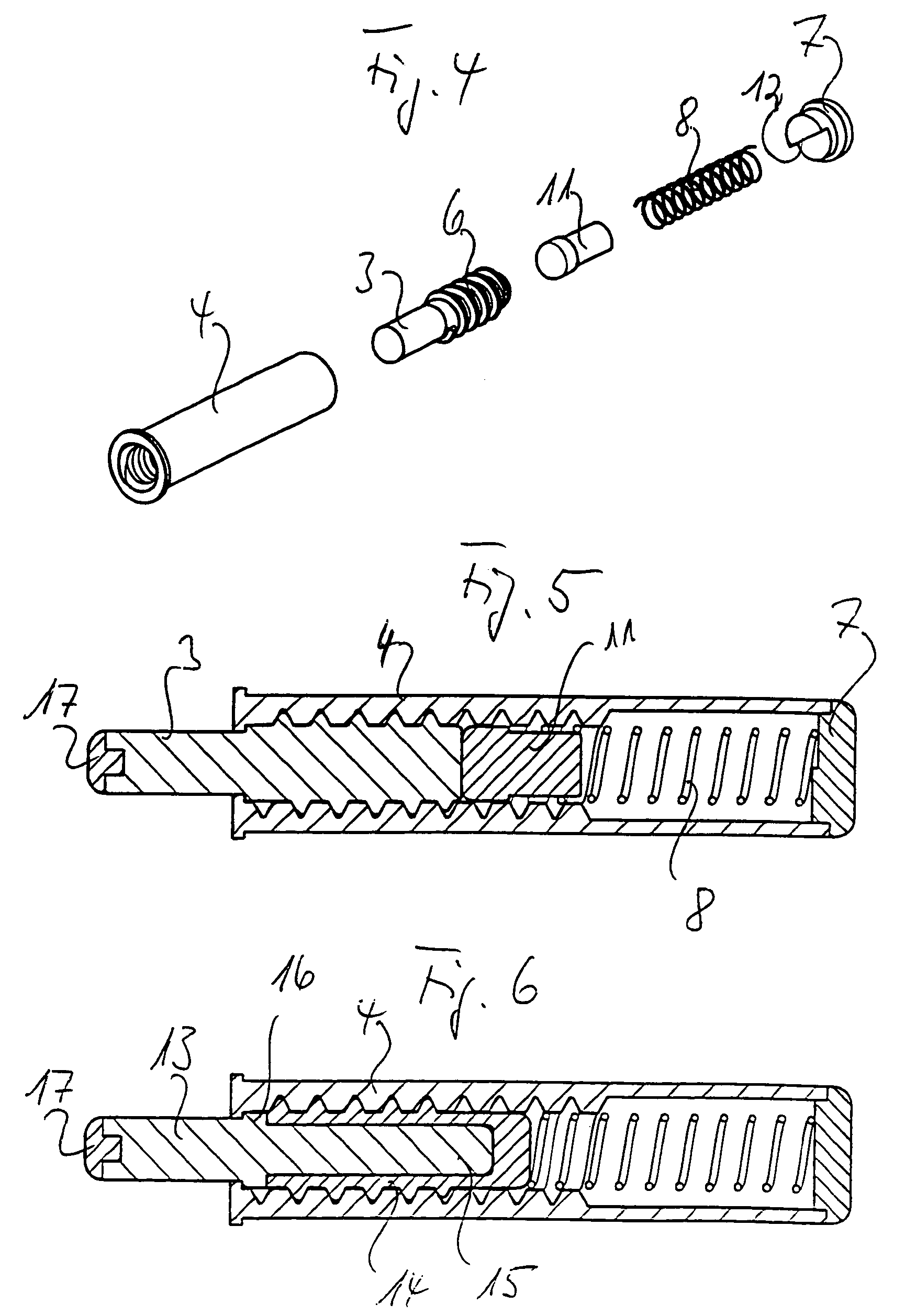
[0040]FIGS. 2 and 3 show a first embodiment of the damping device according to the invention. Said damping device comprises a cylinder 4 which at its open end comprises an internal screw thread 5. The external screw thread 6 of the plunger 3 is screwed into this internal thread so that there is some play. The right part of the cylinder 4 comprises smooth walls without an internal screw thread, as shown. The cylinder 4 is closed off by a cover 7. A compression spring is restrained between the cover 7 and the plunger 3. Between its screw-thread section 6 and its round, smooth-walled section 3 which comes out of the cylinder, the plunger comprises a step 9 by which said plunger is suppor...


PUM


Abstract

The invention relates to a damping device for movable furniture parts, for example for doors or drawers, comprising a piston or plunger which is slidably guided in a hollow body, e.g. a cylinder, with said piston or plunger being impinged upon by spring force into its pushed-out position. According to the invention, the hollow body comprises at least one section of a spiral-shaped stay of the internal screw thread, and/or the piston or plunger comprises at least one section of a spiral-shaped stay of the external screw thread. The stays of the screw threads are glidingly supported one on top of the other, or cams or journals of the hollow body or of the piston or plunger are supported on a screw-thread section of the other component. The pitch of the stays of the screw threads is greater than the pitch at which self-locking occurs.

Description

BACKGROUND OF THE INVENTION[0001]The invention relates to a damping device for movable furniture parts, for example for doors or drawers, comprising a piston or plunger which is slidably guided in a hollow body, e.g. a cylinder, with said piston or plunger being impinged upon by spring force into its pushed-out position.[0002]Devices of this type are used for decelerating movable furniture parts, for example doors, flaps or drawers, during vigorous movement into their closed position so as to reduce noise when they come to rest against carcass parts of items of furniture or fixed parts, and so as to reduce impact loads. In known devices of this type, the damping devices which are used for damping or decelerating the furniture parts are impinged upon along only a relatively small path in the closing region of the movable furniture parts so that they are only able to provide a correspondingly modest damping or deceleration action.[0003]In the older utilities models 20 302 524.4 and 20...

Claims


Application Information

Patent Timeline
Patent Type & Authority Patents(United States)
IPC IPC(8): B60T7/12B60G15/02E05F5/08A47B96/00E05D5/08E05F5/02E05F5/10F16F7/00F16F7/06
CPCE05F5/006E05F5/02E05Y2201/21E05Y2201/254E05Y2201/256E05Y2201/264E05Y2201/266E05Y2201/696E05Y2600/45E05Y2600/46E05Y2900/20E05Y2201/608A47B96/00
Inventor SALICE, LUCIANO
Owner ARTURO SALICE
Why Eureka
Try Eureka