Method and apparatus for data recovery

a data recovery and data technology, applied in the field of data recovery methods and apparatuses, can solve the problems of high-resolution, high-cost analog-to-digital converters, and incorrect decoding during data retrieval, and achieve the effect of lowering the data error ra

Active Publication Date: 2007-06-26
AUTOCHIPS
View PDF4 Cites 13 Cited by
  • Summary
  • Abstract
  • Description
  • Claims
  • Application Information

AI Technical Summary

Benefits of technology

[0007]It is therefore the object of the present invention to provide a method and apparatus suitable for high data density recovery that can effectively lower the data error rate.
[0012]In another aspect of the present invention, an apparatus for data recovery is provided. The apparatus includes a multi-level comparison unit, a detection logic unit, and a data composer. The multi-level comparison unit compares an input signal with M different reference signal levels to generate M digital data, the number M being greater than or equal to 2. The detection logic unit performs logic operations upon specified lengths over the M digital data to obtain a result. The data composer generates recovered data conforming with the run length encoding constraint based on the M digital data obtained from the multi-level comparison unit and the result from the detection logic unit. Therefore, the present invention can effectively lower the data error rate.

Problems solved by technology

As a result, encoded data with run length equal to (d) or (d′) and (k) or (k′) will be affected by low frequency noise, causing incorrect decoding during data retrieving.
Nevertheless, a high-resolution but higher cost analog-to-digital converter is required.

Method used


Image

  • Method and apparatus for data recovery
  • Method and apparatus for data recovery
  • Method and apparatus for data recovery

Examples


second embodiment

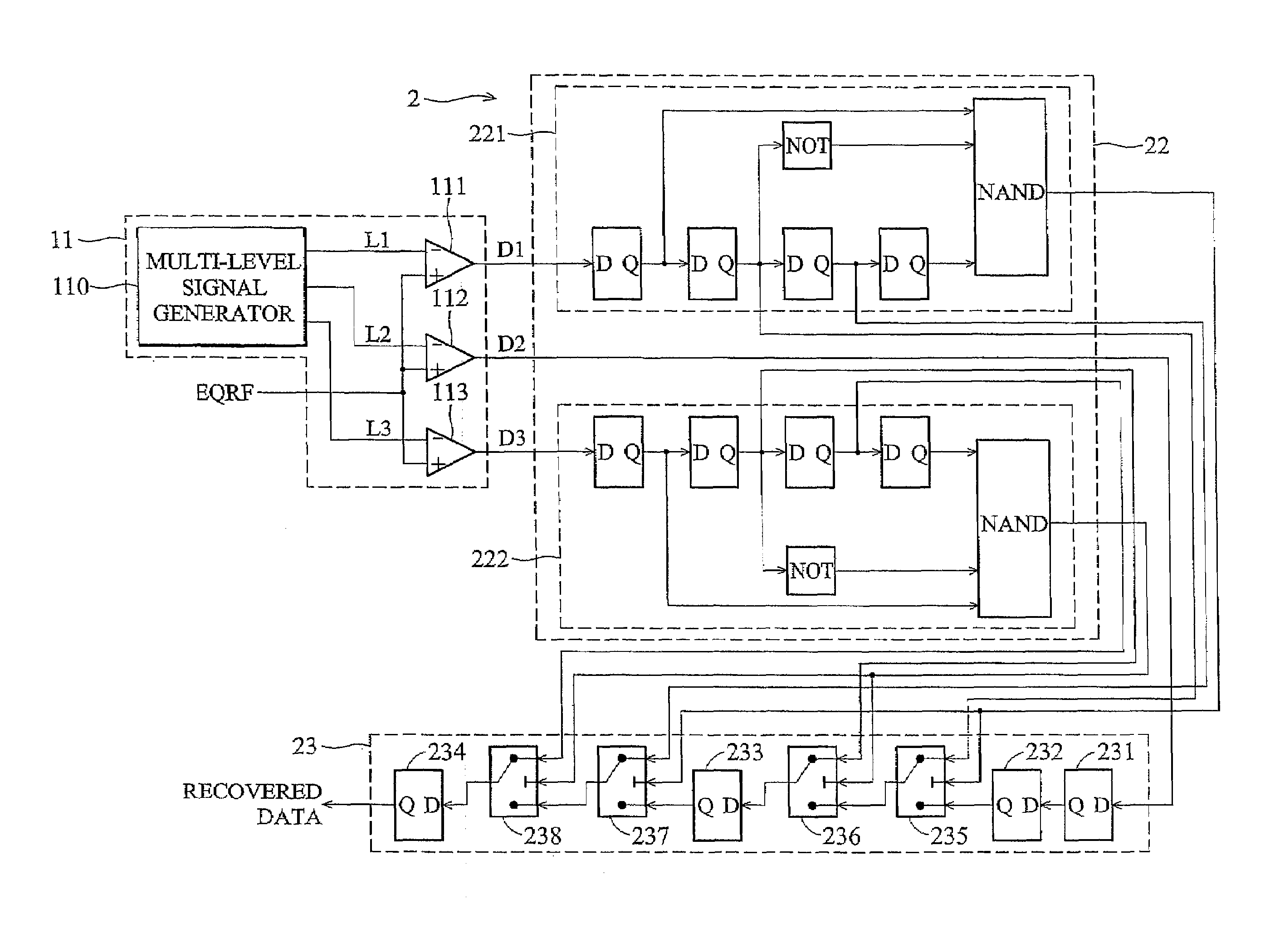
[0044]FIG. 10 shows a detailed schematic circuit diagram of a data decoding apparatus 2 in the second preferred embodiment of the present invention. Different from the first preferred embodiment, in the second embodiment, aside from being able to detect data segments (0110 or 1001) of the digital data with the minimum run length limit (d′), the apparatus 2 can further detect data segments (0100 or 1011) of the digital data with the minimum run length limit (d′−1). As illustrated, the apparatus 2 also includes a multi-level comparison unit 11, a detection logic unit 22, and a data composer 23. The detection logic unit 22 includes first and second detection circuits 221, 222. The first detection circuit 221 of the detection logic unit 22 includes four cascaded D-type flip-flops, a NOT gate, and a three-input NAND gate. The first D-type flip-flop receives the digital data (D1). The NOT gate is connected to an output of the second D-type flip-flop. The NAND gate is connected to outputs ...

third embodiment

[0048]FIG. 13 shows a detailed schematic circuit diagram of the third preferred embodiment of an apparatus 3 for data recovery of the present invention. Different from the previous two embodiments, in the third embodiment, the multi-level comparison unit 31 of the apparatus 3 relies upon seven reference signal levels (L1–L7) when decoding the input signal (EQRF). Particularly, three of the reference signal levels (L1–L3) are compared with the input signal (EQRF) by three corresponding comparators 311 so as to generate corresponding sets of digital data (D1–D3) provided to first, second and third detection circuits 321, 322, 323 of the detection logic unit 32, respectively. The constructions of the detection circuits 321, 322, 323 are similar to that of the first detection circuit 121 in the detection logic unit 12 of the first preferred embodiment. The outputs of the detection circuits 321, 322, 323 are then fed to an AND gate. Another three of the reference signal levels (L5–L7) ar...


PUM

PropertyMeasurementUnit
run lengthaaaaaaaaaa
lengthaaaaaaaaaa
bias voltageaaaaaaaaaa

Abstract

An apparatus for data recovery includes a multi-level comparison unit, a detection logic unit, and a data composer. The multi-level comparison unit compares an input signal with M different reference signal levels to generate M digital data, the number M being greater than or equal to 2. The detection logic unit is coupled to the multi-level comparison unit, and performs logic operations upon specified lengths over the M digital data obtained from the multi-level comparison unit. The data composer is coupled to the multi-level comparison unit and the detection logic unit. The data composer generates recovered data conforming with a run length encoding constraint based on the M digital data obtained from the multi-level comparison unit and the result obtained from the detection logic unit.

Description

CROSS-REFERENCE TO RELATED APPLICATION[0001]This application claims priority of Taiwanese application no. 092130799, filed on Nov. 4, 2003.BACKGROUND OF THE INVENTION[0002]1. Field of the Invention[0003]The invention relates to a method and apparatus for data recovery, and more particularly, to a method and apparatus for data recovery suitable for high-density data recording applications, that can effectively lower the data error rate.[0004]2. Description of the Related Art[0005]When transmitting data and when recording data on a recording medium, such as a floppy disk, an optical disc or a magneto-optic disc, data are modulated into another encoded data format based on a specific encoding rule for suitability to transmission or recording. In order to correctly receive and retrieve the encoded data from the recording medium, the length of the encoded data must conform with a run length limit (abbreviated as RLL). Taking the DVD system as an example, the run length of the RLL encoded...

Claims


Application Information

Patent Timeline
Patent Type & Authority Patents(United States)
IPC IPC(8): H03M7/00G06F11/00G06F11/30G08C25/00G11B20/10G11B20/14H03M13/00H04L1/00
CPCG11B20/10009G11B20/1426
Inventor CHENG, YUHLIU, PI-HAI
Owner AUTOCHIPS
Why Eureka
Try Eureka