Method and apparatus for determining recording pulse parameters for an optical disc

Inactive Publication Date: 2007-06-26
PANASONIC CORP
View PDF19 Cites 5 Cited by
  • Summary
  • Abstract
  • Description
  • Claims
  • Application Information

AI Technical Summary

Benefits of technology

[0057]As noted above, in an optical disc recording parameter determining method that reads standard recording pulse parameters from a writable optical disc having standard recording pulse parameters prerecorded to a specific area thereof, and sets the recording pulse parameters of the recording and reproducing device for reading and writing data, the optical disc recording parameter determining method according to the present invention can reduce the effects of variation in the characteristics of the writable opt

Problems solved by technology

Because the size of the recorded marks and the distance of the space between marks is so small in high density recording, the heat of the laser light applied to form a pa

Method used


Image

  • Method and apparatus for determining recording pulse parameters for an optical disc
  • Method and apparatus for determining recording pulse parameters for an optical disc
  • Method and apparatus for determining recording pulse parameters for an optical disc

Examples


Example

EMBODIMENT 1

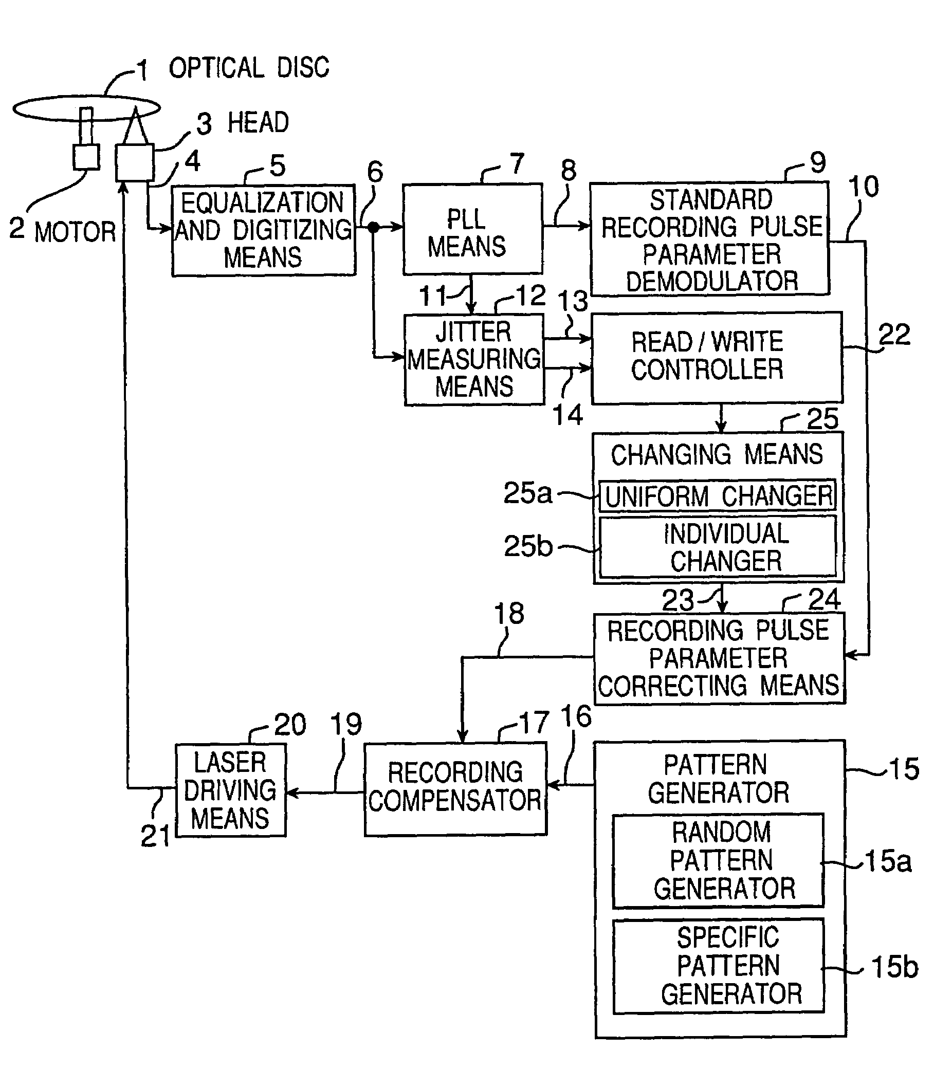
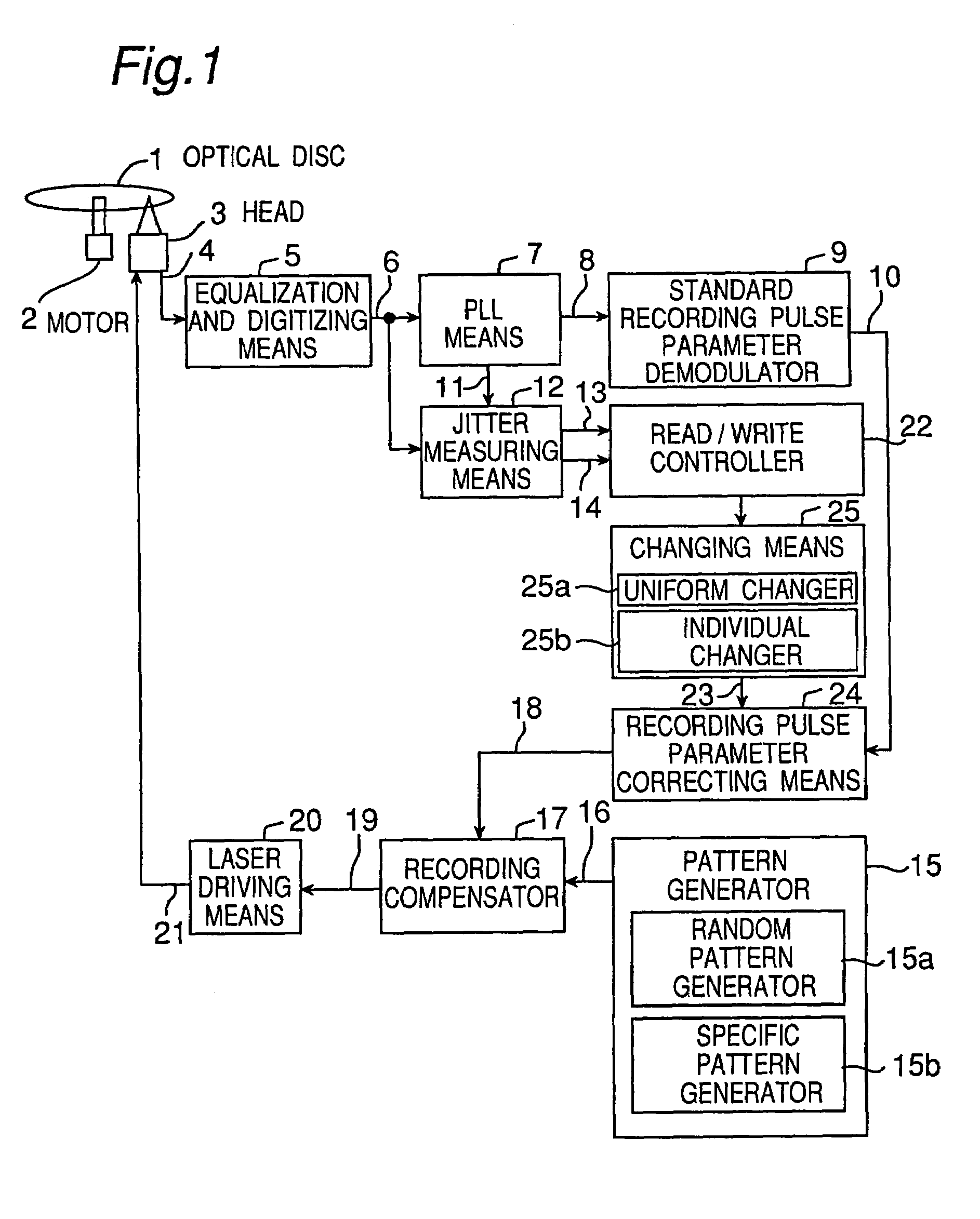
[0075]FIG. 1 is a block diagram of an optical disc recording and reproducing device that implements the optical disc recording parameter determining method of the present invention. The components and signals of this device are described first. Reference numeral 1 is a writable phase-change type optical disc; reference numeral 2 is a motor for rotating the optical disc 1; reference numeral 3 is a head for reading recorded data from the rotating optical disc 1 and obtaining read signal 4; reference numeral 5 is an equalization and digitizing means for obtaining a digital binary signal 6 from the analog read signal by means of a duty feedback slice method after compensating the frequency characteristic of read signal 4; reference numeral 7 is a PLL for detecting the edge of binary signal 6, generating a read clock synchronized thereto, and converting the binary signal 6 to data 8 synchronized to the read clock, and outputting as phase difference pulse 11 the time-based off...

Example

EMBODIMENT 2

[0097]Described next below is a specific optical disc recording parameter determining method whereby good recording characteristics can be achieved with a writable optical disc wherein standard recording pulse parameters are recorded to a specific disc area even when there is a difference between the optical disc characteristics and standard recording pulse parameters. This second embodiment of the invention is also described with reference to FIG. 1. Those parts that differ from the above first embodiment are described below while further description of the same parts is omitted. In this embodiment two of the eighteen recording pulse parameters, that is, 5Ts5Tm and 5Tm5Ts, use the standard recording pulse parameters as is. Twelve different corresponding recording patterns are used to determine the remaining sixteen recording pulse parameters. These twelve recording patterns are generated by the specific pattern generator 15b of the pattern generating means 15.

[0098]The ...

Example

EMBODIMENT 3

[0116]Next is described a specific method for reducing the number of read / write operations and shortening time required when compared with the steps of the second embodiment.

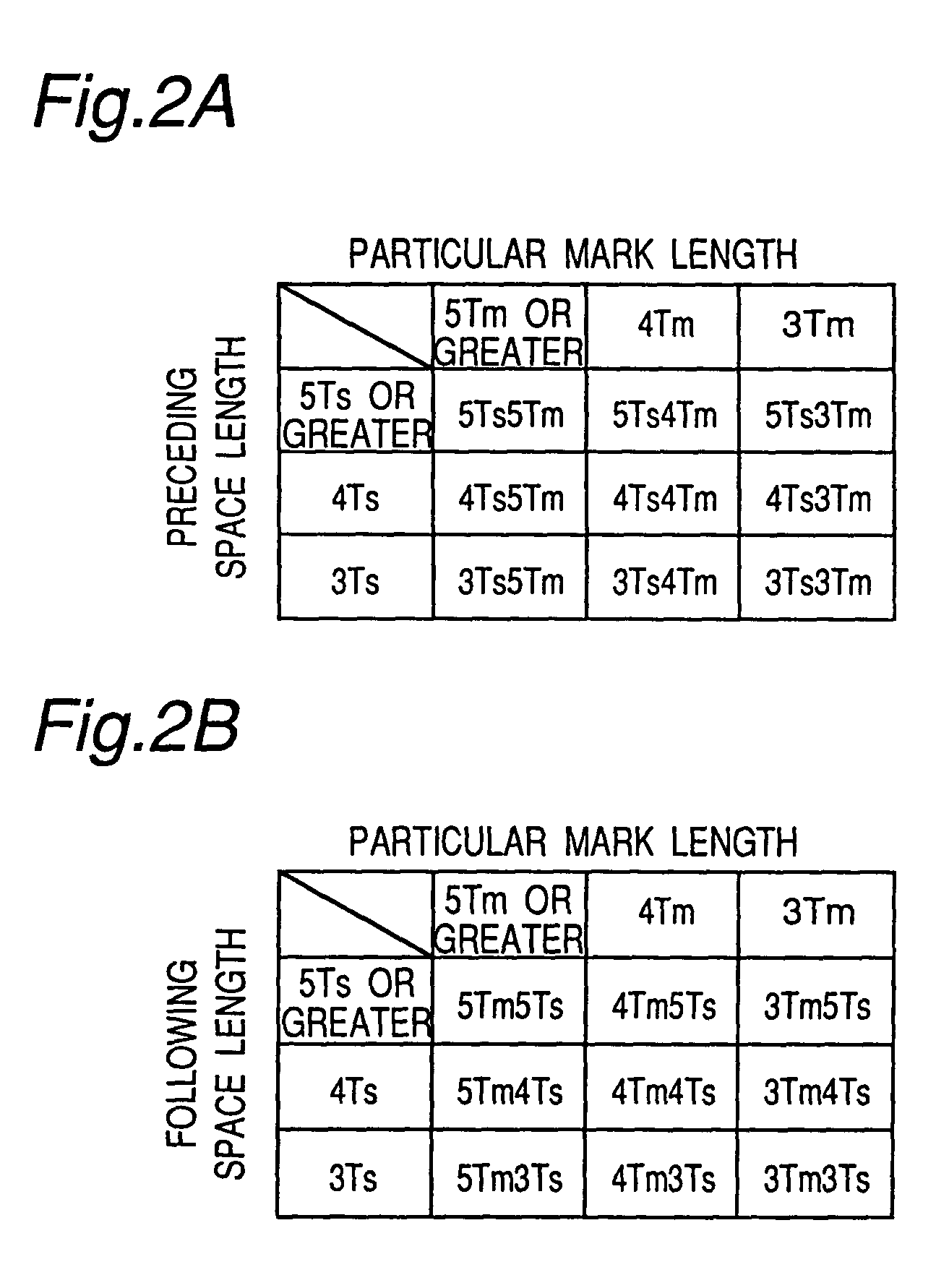
[0117]When the leading mark-edge pulse parameter is 5Ts3Tm in FIG. 2, the correction value is determined as described in the above-noted second embodiment using recording pattern (3) in FIG. 7. When the leading mark-edge pulse parameter is 3Ts3Tm in FIG. 2, the correction value is determined using recording pattern (11) in FIG. 7. Then, when the leading mark-edge pulse parameter is 4Ts3Tm, the correction value is not determined using recording pattern (7), but rather is calculated by, for example, interpolating the 4Ts3Tm correction value from the relationship between the 5Ts3Tm correction value as determined above, the 5Ts3Tm value of the standard parameters, the 3Ts3Tm correction value as determined above, the 3Ts3Tm value of the standard parameters, and the 4Ts3Tm value of the standard parameters....


PUM


Abstract

If data is recorded using a disc with deviating characteristics and a recorder with deviating characteristics, data will not be appropriately recorded, and errors will occur in the read signal. Standard recording pulse parameters specifying recording pulse positions for plural possible mark length and space length combinations are read from a writable optical disc, these standard recording pulse parameters are then used for test writing, the standard recording pulse parameters are changed uniformly or individually, a best recording pulse parameter is thus obtained, and jitter can be reduced.

Description

[0001]This is a divisional application of Ser. No. 09 / 582,675, filed Jun. 29, 2000, now U.S. Pat. No. 6,791,926 which corresponds to International Application PCT / JP99 / 06158, filed Nov. 5, 1999.TECHNICAL FIELD[0002]The present invention relates to a method and apparatus for determining the recording pulse parameters of an optical disc by reading standard recording pulse parameters from a writable optical disc, the optical disc having standard recording pulse parameters prerecorded to a specific area thereof, setting the recording pulse parameters of a recording and reproducing device, and recording or reproducing data from the disc.BACKGROUND ART[0003]The DVD-RAM specification describes one example of a high data capacity rewritable optical disc, and devices capable of writing 2.6 gigabytes of data using a mark edge recording method to one side of a 12 cm diameter disc using a phase change recording film are available. Looking to achieve an even higher density optical disc medium, t...

Claims


Application Information

Patent Timeline
IPC IPC(8): G11B5/09G11B7/0045G11B7/006G11B7/007G11B7/013G11B7/125G11B20/10G11B20/18
CPCG11B7/0045G11B7/0062G11B7/126G11B20/10009G11B20/10194G11B20/182G11B7/007G11B7/24085G11B7/00456G11B20/10398G11B2220/2537
Inventor FURUMIYA, SHIGERUMINAMINO, JUNICHISHOJI, MAMORU
Owner PANASONIC CORP
Why Eureka
Try Eureka