
Forward link time delay for distributed antenna system

a technology of forward link and antenna system, which is applied in diversity/multi-antenna system, digital transmission, polarisation/directional diversity, etc., can solve the problems of physical separation of antenna elements that can give rise to phase differences and consequent signal distortion, and difficulty for the receiver to resolve a desired signal

Inactive Publication Date: 2007-06-26
SPRING SPECTRUM LP
View PDF19 Cites 28 Cited by
  • Summary
  • Abstract
  • Description
  • Claims
  • Application Information

AI Technical Summary

Benefits of technology

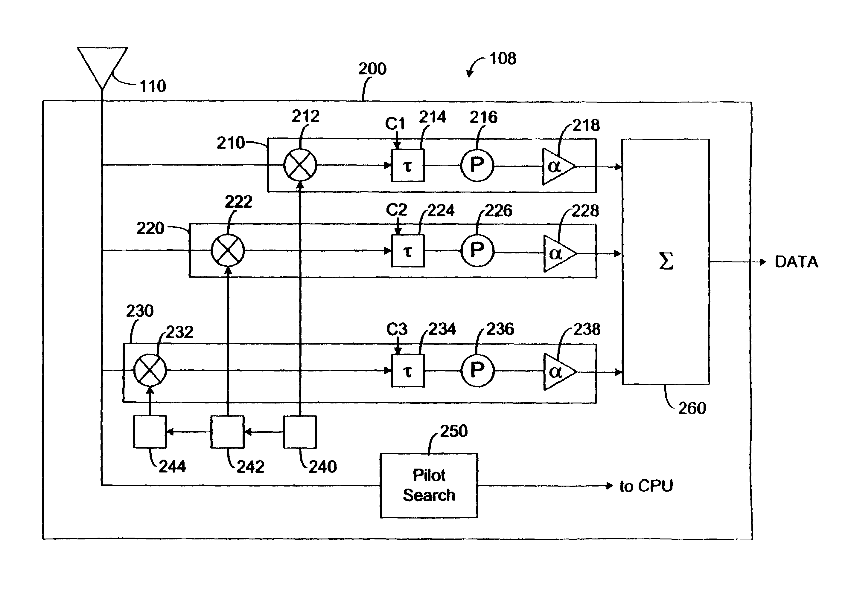
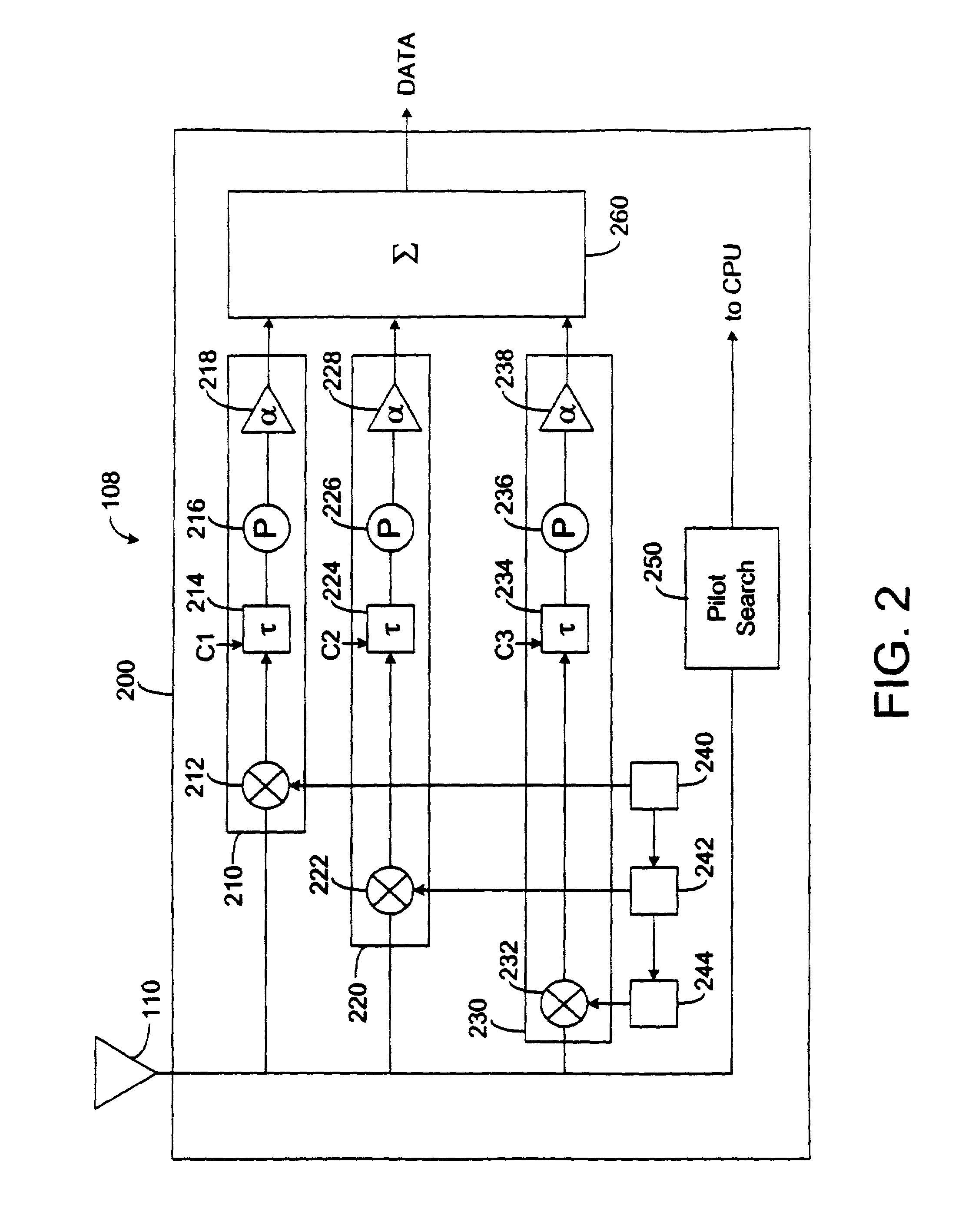
[0019]According to one aspect of the invention, a separate delay element may be provided for each signal transmitted from an antenna element, so as to deliver each air interface link with a time delay sufficient to allow a rake receiver to resolve the signals. Typically, a rake receiver will be able to resolve signals that are at least ⅛ chip apart from each other. The exemplary embodiment may therefore offset the receiving times of signals substantially more than ⅛ chip and synchronize the receiver with the transmitting antenna to trivialize the inherent phase differences between the various antenna elements.
[0021]In another embodiment, the rake receiver may take advantage of multi-path signaling due to the adjusted time delays. An antenna system may be used to transmit signals to the rake receiver. Each finger of the rake receiver may be tuned to an antenna of the system according to the transmission time of the signal from the antenna. This may allow for the rake receiver fingers to be optimally set to receive an optimal signal containing a sufficient amount of power.
[0022]In yet another embodiment, a time delay element may be implemented within the transmitting antennas of an antenna system. A corresponding delay due to the path and distance that a signal may travel may be pre-calculated and set in the transmitting antennas. The antennas of an antenna system may transmit signals at times according to the calculated delays. All of the antennas in the antenna system may transmit the same signal and the rake receiver fingers may individually be tuned to a separate antenna in order to take advantage of multi-path signaling. The rake receiver may potentially receive many reliable signals from each antenna. The rake receiver may be optimally receiving each signal transmitted from each antenna in the antenna system.
[0025]The invention may thereby allow for an optimal and efficient use of rake receivers. It is therefore desirable to configure a mobile communications network to provide a time delay component for each signal to be transmitted to a rake receiver. The present invention provides a mechanism for take advantage of multi-path signaling.

Problems solved by technology

It may be difficult for the receiver to resolve a desired signal from apparent stronger signals received.
On both the forward link (communications from the base station to the mobile station) and reverse link (communications from the mobile station to the base stations), the physical separation of the antenna elements can give rise to phase differences and consequent signal distortion (e.g., cancellation, etc.).
This may cause multiple problems.
As a result, a loss of time alignment can cause interference among the various forward link traffic channels.
Interference problems can also occur when there is a phase misalignment between the transmitted pilot and other Walsh channels.
Interference may hinder the possibility of successfully receiving the transmitted signal.
Any phase misalignment between the receiver and its incoming Walsh channel results in interference between the spreading sequences.
Phase errors are essentially a loss of orthogonality between I and Q. These phase errors can result from crosstalk between I and Q in the base station baseband processing section, misaligned local oscillators, intermodulation (IM) between Walsh codes, or signal distortion due to the physical separation of the transmitting antenna elements.

Method used


Image

  • Forward link time delay for distributed antenna system
  • Forward link time delay for distributed antenna system
  • Forward link time delay for distributed antenna system

Examples


Embodiment Construction

[0034]The present invention relates to a method and apparatus for optimizing the combined signal strength obtained using a rake receiver. In the present invention, a variable delay element is provided for rake receiver finger for the purpose of offsetting the receiving times of each signal sent and received by a rake receiver. The delay of each variable delay element is calibrated to a signal transmitted from an antenna in a CDMA distributed antenna system.

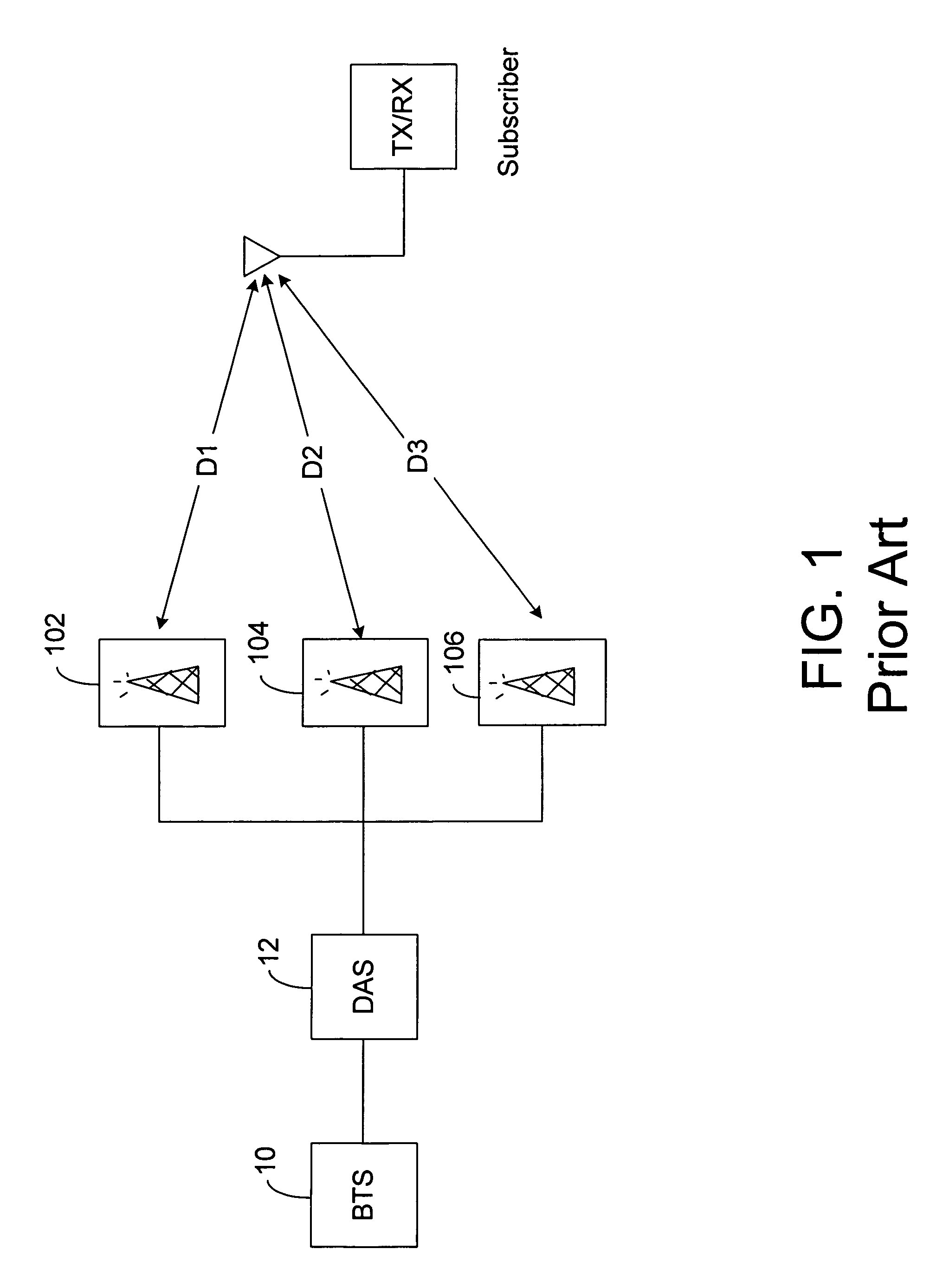
[0035]Referring to FIG. 1, an example of a wireless system is shown that is suitable for application of the present invention. In FIG. 1, an antenna system is shown that includes a first antenna 102, a second antenna 104, and a third antenna 106 that may be used for transmitting signals to a stationary receiver 108. The signals from antennae 102, 104 and 106 are transmitted across an air interface to receiver 108. A receiver 108 is used to receive the transmitted signals. The rake receiver 108 includes an antenna 110 for receiving...


PUM


Abstract

An apparatus and method are shown for receiving multi-path signals. A rake receiver is used to receive multi-path signals. The rake receiver contains multiple fingers that act as correlators, where each finger is synchronized to one of the multi-path signals. Each finger of the rake receiver includes a variable delay element. The delay of the variable delay element in each finger may be determined by calculating the amount of time for a signal to travel from an antenna to the receiver, due to the path traveled, and setting the delay based on the measured travel time. The delay of the variable delay element in each finger may also be determined by scanning through a range of delays of the variable delay element and measuring an output signal level of the finger, the variable delay element then being set to the delay corresponding to the highest measured output signal level.

Description

FIELD OF THE INVENTION[0001]The present invention is directed to a method and system for improving air interface communications in a distributed antenna system.BACKGROUND OF THE INVENTION[0002]Wireless communication is an increasingly popular means of personal communication in the modern world. People are using wireless networks for the exchange of voice and data as an alternative to using a wire infrastructure. In principle, a user can seek information over the Internet or call anyone over a Public Switched Telephone Network (PSTN) from any place inside the coverage area of the wireless network.[0003]With the increase of the popularity of wireless communications, many of the uses for a wire infrastructure are being replaced by wireless infrastructures. For example, a traditional wire infrastructure PBX may be replaced by a wireless PBX to route phone calls and Internet connections in an office. A wireless PBX may take advantage of wireless communication techniques.[0004]A wireless ...

Claims


Application Information

Patent Timeline
IPC IPC(8): H04B1/00
CPCH04B1/7115H04B1/7113
Inventor POPE, JOHN
Owner SPRING SPECTRUM LP
Learn More