Process for controlling the cooling air mass flow of a gas turbine set

a gas turbine and cooling air mass technology, applied in the direction of machines/engines, efficient propulsion technologies, mechanical apparatus, etc., can solve the problem that the control in dependence on cooling air mass flow alone does not give the best result in all circumstances

Inactive Publication Date: 2007-07-03
ANSALDO ENERGIA IP UK LTD
View PDF38 Cites 46 Cited by
  • Summary
  • Abstract
  • Description
  • Claims
  • Application Information

AI Technical Summary

Benefits of technology

[0011]The cooling power in the compressor can be determined among other things and in a particularly simple manner by sensing the temperature difference over an interstage cooler.

Problems solved by technology

However, it is found that, precisely in operation with stronger cooling of the flow in the compressor, a control in dependence on cooling air mass flow alone does not give the best result in all circumstances.

Method used


Image

  • Process for controlling the cooling air mass flow of a gas turbine set
  • Process for controlling the cooling air mass flow of a gas turbine set
  • Process for controlling the cooling air mass flow of a gas turbine set

Examples


Embodiment Construction

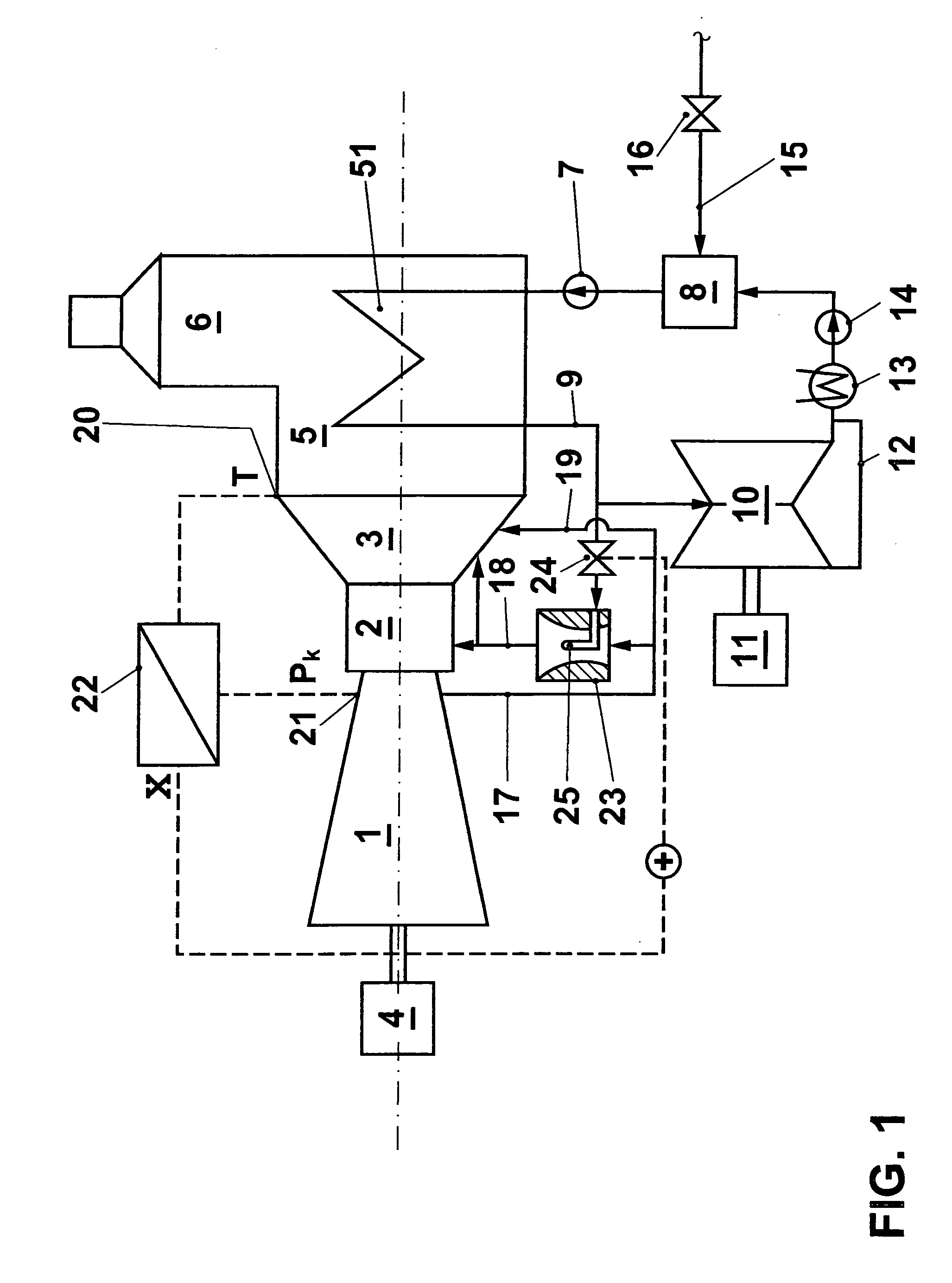
[0033]In the example shown in FIG. 1, a gas turbine set is shown according to an embodiment of the invention, integrated into a combination plant. A compressor 1 compresses air to a pressure, and delivers this into a combustor 2. A fuel is burned in the compressed air in the combustor. The resulting hot flue gases flow through a turbine 3, where they provide power to drive the compressor and an external shaft power user such as a generator 4. The expanded flue gases, which are still at a high temperature, pass through a waste heat steam generator 5 and there heat and evaporate a feedwater mass flow, flowing over heating surfaces 51 there, before they flow out into the atmosphere via a chimney 6. On the steam side, a feed pump 7 delivers a water mass flow from a container 8 into the heat exchanger 51, where this water evaporates and the resulting steam is superheated. Live steam 9 flows to a double-pass steam turbine 10, where the steam is expanded. The steam turbine drives a generat...


PUM


Abstract

A process is provided for the control of the amount of cooling air of a gas turbine set. Suitable means are provided in the cooling system to enable the amount of cooling air to be varied. The control of this means takes place in dependence on an operating parameter (X). This operating parameter is made dependent on the fuel type used.

Description

CROSS-REFERENCE TO RELATED APPLICATIONS[0001]This application is a continuation of the U.S. National Stage designation of co-pending International Patent Application PCT / IB02 / 04520 filed Oct. 30, 2002, the entire content of which is expressly incorporated herein by reference thereto.FIELD OF THE INVENTION[0002]The invention relates to a process for controlling the cooling air mass flow of a gas turbine set.BACKGROUND OF THE INVENTION[0003]Interstage cooling in the compressor of a gas turbine set is a well-known measure which can substantially contribute to an increase of the efficiency factor and the performance of a gas turbine set, particularly when the heat removed from the partially compressed working medium can be usefully employed at a place in the power station. EP 515 995 proposes in this regard to conduct the compressor air through a steam generator, and thus to produce an amount of steam which can be further used in the water-steam circuit of a combination plant. EP 781 90...

Claims


Application Information

Patent Timeline
Patent Type & Authority Patents(United States)
IPC IPC(8): F02C7/143F02C7/18F01K23/10
CPCF01K23/10F02C7/18F02C7/185F05D2260/2322F05D2260/212Y02T50/60
Inventor HOFFMANN, JURGENROFKA, STEFANWALCHLI, RENE
Owner ANSALDO ENERGIA IP UK LTD
Why Eureka
Try Eureka