Resettable latching MEMS temperature sensor apparatus and method

a technology of temperature sensor and latching device, which is applied in the direction of relay, protective switch details, generator/motor, etc., can solve the problems of low power and unpowered temperature sensor currently, not in a form factor suitable for integration with microdevices, and not manufactured using techniques that are compatible with microelectronics or micro-electromechanical systems

Active Publication Date: 2007-07-03
MORGAN RES CORP
View PDF26 Cites 24 Cited by
  • Summary
  • Abstract
  • Description
  • Claims
  • Application Information

AI Technical Summary

Benefits of technology

[0017]It is yet another object of the present invention to provide a micromachined temperature sensor that is easily re-set for reuse.

Problems solved by technology

Low power and unpowered temperature sensors currently exist.
However, they are large-scale devices such as bimetallic strips in standard thermostats.
These devices operate in a somewhat similar fashion (albeit on a much larger scale) and provide a somewhat similar function as the present invention, but are not in a form factor suitable for integration with microdevices, and are not fabricated using techniques that are compatible with microelectronics or micro-electromechanical systems (“MEMS”) devices.
The fundamental problem is that such a system must continuously power the temperature sensor and analog trigger circuitry, creating a constant power draw on the batteries.
Even using the latest in low-power devices and highest capacity batteries, systems that continuously power any sensor will only operate for 5-10 years.
As embedded miniature sensors get smaller, and as batteries are reduced in size and capacity, the use of lower power and unpowered devices will become more critical.
For example, U.S. Pat. No. 5,917,226, entitled “Integrated Released Beam, Thermo-mechanical Sensor for Sensing Temperature Variations and Associated Methods,” provides an integrated circuit for sensing temperature variations using a thermal bimorph device, but the sensor does not have a latching function and does not operate without quiescent power.

Method used


Image

  • Resettable latching MEMS temperature sensor apparatus and method
  • Resettable latching MEMS temperature sensor apparatus and method
  • Resettable latching MEMS temperature sensor apparatus and method

Examples


Embodiment Construction

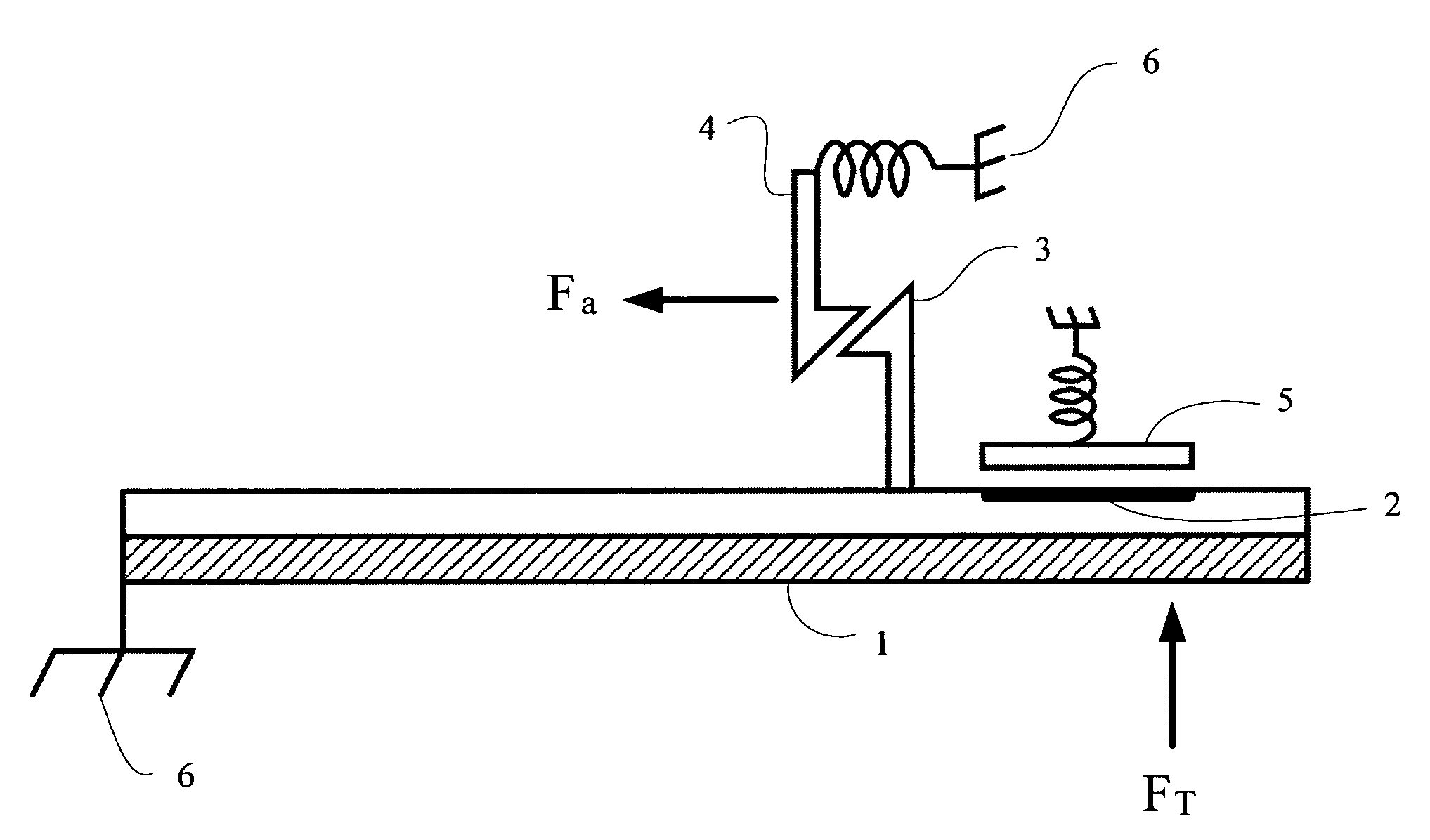
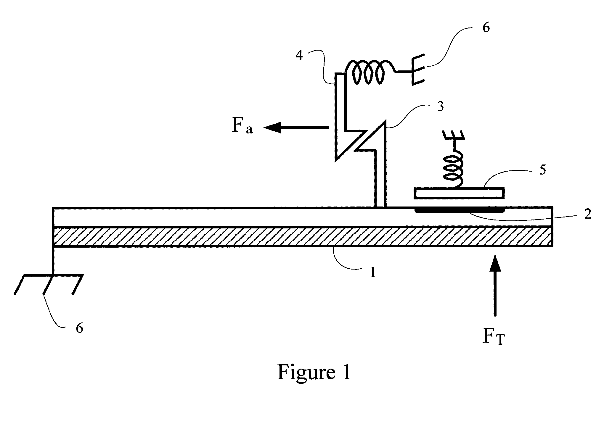
[0033]The illustrated embodiment of the invention is fabricated in a thick layer of silicon or other conductor material. Within this thick layer of material, a thermal bimorph, a set of flexures, multiple contacts, multiple latch and pawl structures, multiple actuators, and multiple anchors and pads are fabricated. The thermal bimorph consists of a cantilever beam made from the conductor material and a sidewall coating of a different material with a coefficient of thermal expansion mismatch to the conductor material. Upon application of a temperature load, the thermal bimorph will bend so that the free end moves in a lateral direction (i.e., in a direction parallel to the substrate).

[0034]FIG. 1 illustrates a schematic diagram of one embodiment of the invention. The invention utilizes a micromachined cantilever bimorph structure 1 attached to the substrate (not illustrated) via anchors 6. The bimorph structure 1 includes a contact area 2 and a latch 3. Under a temperature load, T, t...


PUM


Abstract

The Resettable Latching MEMS Temperature Sensor provides the capability of recording external temperature extremes without consuming electrical power. The device incorporates a thermal bimorph, contacts, latches, and actuators for device reset. The device can be designed, hardwired, or programmed to trigger at various temperature levels. The device can be fabricated in a simple micromachining process that allows its size to be miniaturized for embedded and portable applications. During operation, the device consumes no quiescent power. The device can be configured to close a circuit, switch an interrupt signal, or switch some other electrical trigger signal between devices at the time of a temperature extreme being reached, or it can be configured to latch and be polled at some time after the temperature limit has occurred.

Description

REFERENCE TO RELATED APPLICATIONS[0001]This application claims priority to Provisional Patent Application U.S. Ser. No. 60 / 619,407, entitled “Resettable Latching MEMS Temperature Sensor” and filed on Oct. 15, 2004, which is fully incorporated herein by reference.GOVERNMENT LICENSE RIGHTS[0002]This invention was made with Government support under contract MDA972-03-C-0010, awarded by the Defense Advanced Research Projects Agency (“DARPA”). The Government has certain rights in the invention.BACKGROUND[0003]1. Field of the Invention[0004]The present invention relates generally to a temperature sensor and method for ring temperature. More particularly, the present invention relates to a low-power micro-mechanical temperature sensor using a micromechanical thermal bimorph structure.[0005]2. Background of the Invention[0006]Embedding miniature sensors in products, systems, storage and shipping containers, and other items allows the monitoring of those items to determine health, maintenanc...

Claims


Application Information

Patent Timeline
Patent Type & Authority Patents(United States)
IPC IPC(8): H01H71/16H02N10/00
CPCB81B3/0078H01H37/52B81B2201/032B81B2203/056H01H2001/0047H01H2037/008H01H2300/032
Inventor JENKINS, ARTHUR ANTHONYKRANZ, MICHAEL SCOTTWILLIAMS, MARTY RAY
Owner MORGAN RES CORP
Why Eureka
Try Eureka