
Drill bit lubrication apparatus and method

a lubrication apparatus and drill bit technology, applied in drill bits, cutting machines, earthwork drilling and mining, etc., can solve the problems of excessive wear and torque of the drill string assembly, tendency to break, and each of the prior single-cone drill bits were subject to excessive wear and torque, so as to prolong the life of the bearing and restrict contaminants

Active Publication Date: 2007-07-10
TIGER 19 PARTNERS
View PDF6 Cites 3 Cited by
  • Summary
  • Abstract
  • Description
  • Claims
  • Application Information

AI Technical Summary

Benefits of technology

"The present invention is a lubrication system for a nutating single cone drill bit. The system includes a lubricant chamber in the bit shank that contains a plunger displaceable by drilling fluid to dispense lubricant. The bit shank has a plurality of bearings that retain the cutter body, and a radial dynamic seal to prevent contamination. The bit can also have a low pressure orifice on the distal end of the cutter body to dispense lubricant. The system allows for longer life of the cutter elements and reduces the need for maintenance. The bit can be easily replenished with the lubricant and can be used in drilling oil wells."

Problems solved by technology

Previous single cone drill bits however provided substantial scraping of the cutter elements causing abnormal wear and torque on the drill string assembly.
Each of the prior single cone drill bits were subject to excessive wearing of the cutting elements because at least during some portion of the rotation, the cutter elements were dragged by the circular motion of the bit on the journal across the formation face rather than moved in compressive engagement with the surface.
These cutter elements are designed to have long use lives if used in compression, but have a tendency to break if subjected to side shear or scraping.
Typically, traditional tri-cone bits must be repeatedly tripped out of the borehole due to excessively worn cutter elements.
Since a nutating single cone drill bit allows for longer service life, the extended periods of down-hole use can be limited by the amount of available lubrication sufficient to maintain the bearings of the nutating single cone bit.
Without sufficient lubrication, the bearing can fail prior to the cutter elements of the bit wearing, limiting the usefulness of the nutating single cone drill bit.

Method used


Image

  • Drill bit lubrication apparatus and method
  • Drill bit lubrication apparatus and method
  • Drill bit lubrication apparatus and method

Examples


Embodiment Construction

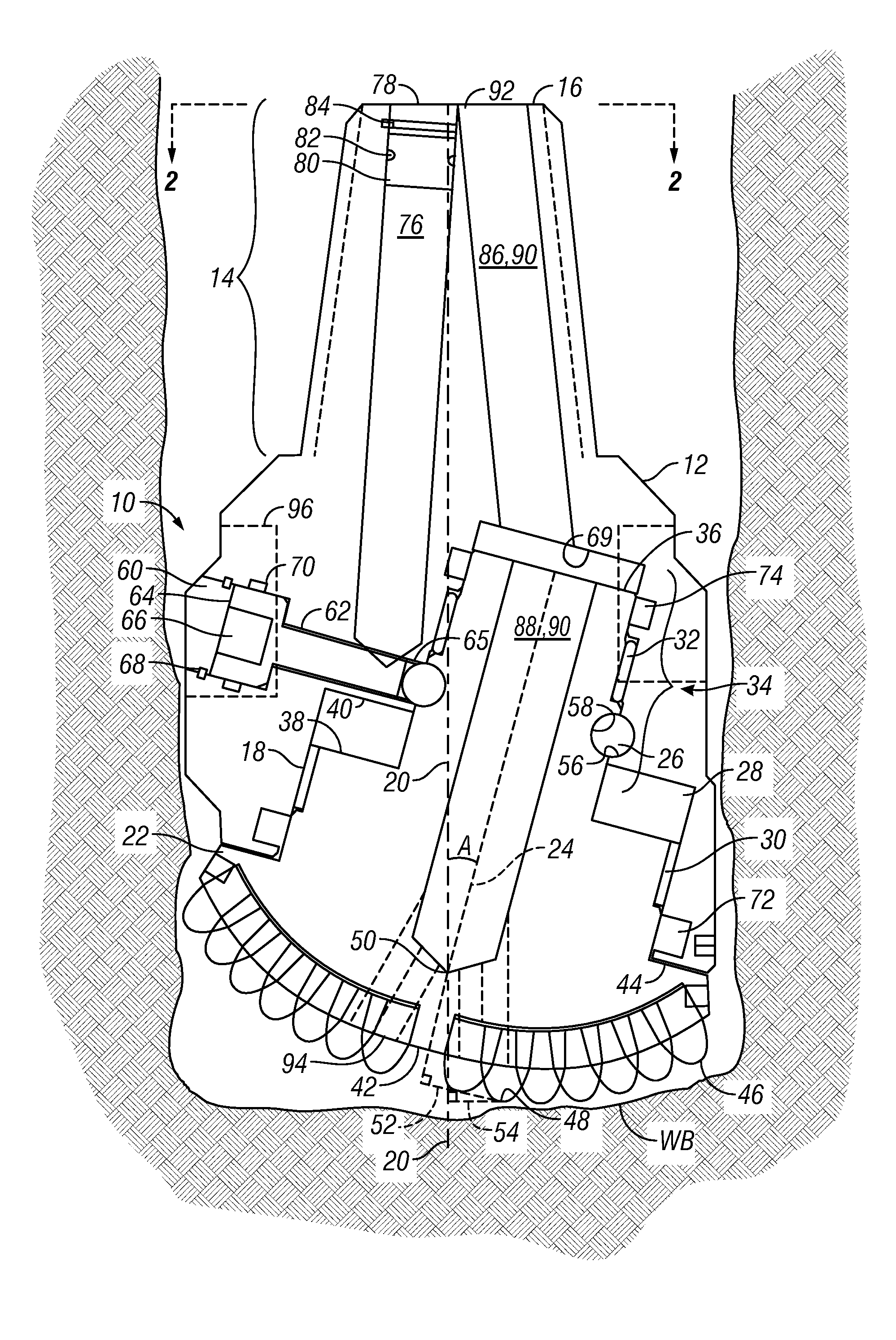
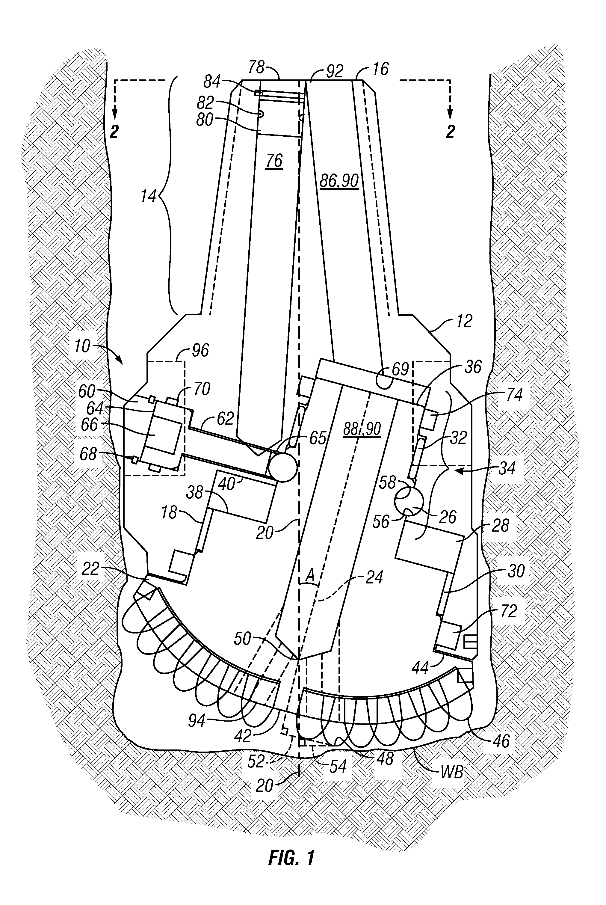
[0015]With reference to the figures wherein like reference numerals are used to refer to like parts, FIG. 1 shows a cross-sectional schematic view of a lubricating nutating single cone drill bit 10. The bit 10 includes a bit shank 12 with a drill string connection 14 adjacent the proximal end 16 and an axially skewed bore 18 formed in a distal end of the bit shank 12. The bore 18 is axially skewed at an acute angle A relative to the axis of the bit shank 12. The axis of rotation 24 of the cutter body 22 can be skewed about 10° from the central axis 20 of the bit shank 12, for example, however any acute skew angle can be utilized, consistent with the disclosure made in U.S. Pat. No. 6,892,828. Cutter body 22 has an outside surface formed respectively to the axially skewed bore 18 to allow at least partial insertion therein. As the cutter body 22 rotates within the axially skewed bore 18, at least one bearing can be disposed therebetween to aid in the rotation. The plurality of bearin...


PUM


Abstract

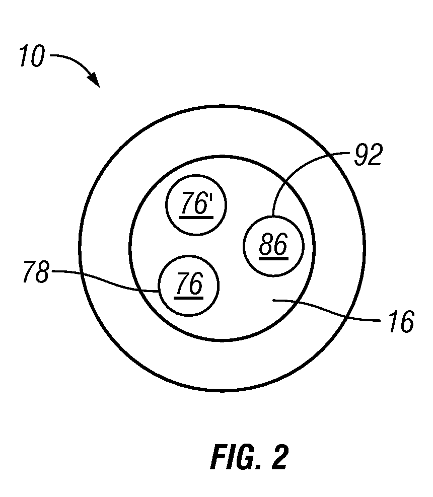
A lubricating nutating single cone drill bit 10 is disclosed. Bit 10 includes a bit shank 12 with an axially skewed bore 18 rotatably retaining a cutter body 22. A plurality of cutter elements (46, 48) are affixed to the cutter body 22. Bearings (26, 28, 30, 32) enable rotation of the cutter body 22 and lubricant is dispensed to the bearings from a lubricant chamber (76, 76′) by a plunger 80 driven by drilling fluid. A method to drill includes attaching the bit 10 to a drill string, engaging the bit 10 into a formation (WB), pumping a drilling fluid into a plunger 80 in the lubricant chamber 76 to dispense lubricant to the bearings (26, 28, 30, 32). The method can include pumping the drilling fluid through a fluid passage 90 in the bit 10 and out of a low pressure orifice 94 on the cutter body 22.

Description

BACKGROUND[0001]The present invention generally relates to drill bits for boring subterranean and sub sea formations. More particularly, the present invention relates to a lubricating nutating single cone drill bit having an axis of rotation skewed relative to the central axis of the bit body in the borehole providing low torque and allowing high compressive loading on the bit assembly.[0002]A number of single cone drill bits have been proposed through the years to drill bore holes for mining, oil and gas exploration, and utility construction. It has been previously recognized that a single cone bit would offer superior design characteristics, such as bearing size permitting greater longitudinal compressive loading on the drill bit. Previous single cone drill bits however provided substantial scraping of the cutter elements causing abnormal wear and torque on the drill string assembly.[0003]Each of the prior single cone drill bits were subject to excessive wearing of the cutting ele...

Claims


Application Information

Patent Timeline
Patent Type & Authority Patents(United States)
IPC IPC(8): E21B10/22
CPCE21B10/086E21B10/24
Inventor RIVES, ALLEN KENT
Owner TIGER 19 PARTNERS
Learn More